Intel BLKDQ35JOE Product Specification - Page 49
Auxiliary Front Panel Power/Sleep LED Header, 2.2.4, Power Supply Connectors
 |
UPC - 200001401862
View all Intel BLKDQ35JOE manuals
Add to My Manuals
Save this manual to your list of manuals |
Page 49 highlights
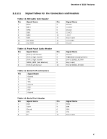
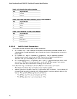
Overview of BIOS Features 2.2.2.3 Auxiliary Front Panel Power/Sleep LED Header Pins 1 and 3 of this header duplicate the signals on pins 2 and 4 of the front panel header. Table 20. Auxiliary Front Panel Power/Sleep LED Header Pin Signal Name 1 HDR_BLNK_GRN 2 Not connected 3 HDR_BLNK_YEL In/Out Out Out Description Front panel green LED Front panel yellow LED 2.2.2.4 Power Supply Connectors The board has the following power supply connectors: • Main power - a 2 x 12 connector. This connector is compatible with 2 x 10 connectors previously used on Intel Desktop boards. The board supports the use of ATX12V power supplies with either 2 x 10 or 2 x 12 main power cables. When using a power supply with a 2 x 10 main power cable, attach that cable on the rightmost pins of the main power connector, leaving pins 11, 12, 23, and 24 unconnected. • Processor core power - a 2 x 2 connector. This connector provides power directly to the processor voltage regulator and must always be used. Failure to do so will prevent the board from booting. Table 21. Processor Core Power Connector Pin Signal Name 1 Ground 3 +12 V Pin Signal Name 2 Ground 4 +12 V Table 22. Main Power Connector Pin Signal Name Pin Signal Name 1 +3.3 V 13 +3.3 V 2 +3.3 V 14 -12 V 3 Ground 15 Ground 4 +5 V 16 PS-ON# (power supply remote on/off) 5 Ground 17 Ground 6 +5 V 18 Ground 7 Ground 19 Ground 8 PWRGD (Power Good) 20 No connect 9 +5 V (Standby) 21 +5 V 10 +12 V 11 +12 V (Note) 12 2 x 12 connector detect (Note) 22 +5 V 23 +5 V (Note) 24 Ground (Note) Note: When using a 2 x 10 power supply cable, this pin will be unconnected. For information about Power supply considerations Refer to Section 2.5.1on page 55 49
-
 1
1 -
2
-
3
-
4
-
5
-
6
-
7
-
8
-
9
-
10
-
11
-
12
-
13
-
14
-
15
-
16
-
17
-
18
-
19
-
20
-
21
-
22
-
23
-
24
-
25
-
26
-
27
-
28
-
29
-
30
-
31
-
32
-
33
-
34
-
35
-
36
-
37
-
38
-
39
-
40
-
41
-
42
-
43
-
 44
44 -
 45
45 -
 46
46 -
 47
47 -
 48
48 -
 49
49 -
 50
50 -
 51
51 -
 52
52 -
 53
53 -
 54
54 -
55
-
56
-
57
-
58
-
59
-
60
-
61
-
62
-
63
-
64
-
65
-
66
-
67
-
68
-
69
-
70
-
71
-
72
-
73
-
74
-
75
-
76
-
77
-
78
-
79
-
80
-
81
-
82
-
83
-
84
 |
 |
