Intel DP67BG Product Specification
Intel DP67BG Manual
 |
View all Intel DP67BG manuals
Add to My Manuals
Save this manual to your list of manuals |
Intel DP67BG manual content summary:
- Intel DP67BG | Product Specification - Page 1
January 2011 Order Number: G13848-001US The Intel® Desktop Board DP67BG may contain design defects or errors known as errata that may cause the product to deviate from published specifications. Current characterized errata are documented in the Intel Desktop Board DP67BG Specification Update. - Intel DP67BG | Product Specification - Page 2
® Desktop Board DP67BG Technical Product Specification Date January 2011 This product specification applies to only the standard Intel® Desktop Board DP67BG with BIOS identifier BGP6710J.86A. Changes to this specification will be published in the Intel Desktop Board DP67BG Specification Update - Intel DP67BG | Product Specification - Page 3
of the hardware used on the Intel Desktop Board DP67BG A map of the resources of the Intel Desktop Board The features supported by the BIOS Setup program A description of the BIOS error messages, beep codes, and POST codes Regulatory compliance and battery disposal information Typographical - Intel DP67BG | Product Specification - Page 4
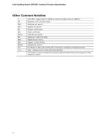
Intel Desktop Board DP67BG Technical Product Specification Other Common Notation # GB GB/s Gb/s KB Kbit kbits/s MB MB/s Mbit Mbits/s xxh x.x V * Used after a signal name to identify an active-low signal (such - Intel DP67BG | Product Specification - Page 5
Feature Summary 9 1.1.2 Board Layout 11 1.1.3 Block Diagram 13 1.2 Legacy Considerations 14 1.3 Online Support 14 1.4 Processor 14 1.5 System Memory 15 1.5.1 Memory Configurations 17 1.6 Intel® P67 Express Chipset 19 1.6.1 PCI Express x16 Graphics 19 1.6.2 USB 19 1.6.3 SATA Interfaces 19 - Intel DP67BG | Product Specification - Page 6
Memory Organization 62 3.3 Resource Configuration 62 3.3.1 PCI Autoconfiguration 62 3.4 System Management BIOS (SMBIOS 63 3.5 Legacy USB Support 63 3.6 BIOS Updates 64 3.6.1 Language Support 64 3.6.2 Custom Splash Screen 65 3.7 BIOS Recovery 65 3.8 Boot Options 66 3.8.1 Optical Drive Boot - Intel DP67BG | Product Specification - Page 7
Audio Jack Support 22 108H 28H 5. LAN Connector LED States 25 109H 289H 6. Effects of Pressing the Power Switch 29 10H 290H 7. Power States and Targeted System Power 30 1H 291H 8. Wake-up Devices and Events 31 12H 29H 9. Diagnostic LEDs 36 13H 293H 10. System Memory Map 41 - Intel DP67BG | Product Specification - Page 8
Header 49 21. States for a One-Color Power LED 50 22. States for a Two-Color Power LED 50 23. BIOS Setup Configuration Jumper Settings 53 24. Recommended Power Supply Current Values 55 25. Fan Header Current Capability 56 26. Thermal Considerations for Components 58 27. Environmental - Intel DP67BG | Product Specification - Page 9
― One port via a front-panel header (blue) • Separate module that provides both Bluetooth* and WiFi included with the desktop board (optional) • Intel® BIOS resident in the SPI Flash device • Support for Advanced Configuration and Power Interface (ACPI), Plug and Play, and SMBIOS continued 9 - Intel DP67BG | Product Specification - Page 10
Intel Desktop Board DP67BG Technical Product Specification Table 1. Feature Summary (continued) Instantly Available PC Technology LAN Support Expansion Capabilities Hardware Monitor Subsystem • Support for PCI* Local Bus Specification Revision 2.2 • Support for PCI Express* Revision 2.0 • Suspend - Intel DP67BG | Product Specification - Page 11
Product Description 1.1.2 Board Layout Figure 1 shows the location of the major components on Intel Desktop Board DP67BG. Figure 1. Major Board Components Table 2 lists the components identified in Figure 1. 11 - Intel DP67BG | Product Specification - Page 12
power button V Onboard reset button W Speaker X Front chassis fan header Y Battery Z Intel P67 Express Chipset AA SATA connectors (6) BB Consumer IR transmitter (output) header CC Consumer IR receiver (input) header DD BIOS Setup configuration jumper block EE Front panel USB - Intel DP67BG | Product Specification - Page 13
Product Description 1.1.3 Block Diagram Figure 2 is a block diagram of the major functional areas of the board. Figure 2. Block Diagram 13 - Intel DP67BG | Product Specification - Page 14
Available configurations for the Intel Desktop Board DP67BG Visit this World Wide Web site: http://www.intel.com/products/motherboard/index.htm http://www.intel.com/p/en_US/support?iid=hdr+support http://ark.intel.com Supported processors Chipset information BIOS and driver updates Tested memory - Intel DP67BG | Product Specification - Page 15
specifications, the board should be populated with DIMMs that support the Serial Presence Detect (SPD) data structure. This allows the BIOS to read the SPD data and program the chipset to accurately configure memory settings for optimum performance. If non-SPD memory is installed, the BIOS will - Intel DP67BG | Product Specification - Page 16
Intel Desktop Board DP67BG Technical Product Specification Table 3 lists the supported DIMM configurations. Table 3. Supported Memory Configurations DIMM Capacity 512 MB Configuration (Note) SS SDRAM Density 1 Gbit SDRAM Organization Front-side/Back-side 64 M x16/empty Number of SDRAM Devices - Intel DP67BG | Product Specification - Page 17
Product Description 1.5.1 Memory Configurations The Intel Core i7, Intel Core i5, and Intel Core i3 processors support the following types of memory organization: • Dual channel (Interleaved) mode. This mode offers the highest throughput for real world applications. Dual channel mode is enabled - Intel DP67BG | Product Specification - Page 18
Intel Desktop Board DP67BG Technical Product Specification Figure 3 illustrates the memory channel and DIMM configuration. Figure 3. Memory Channel and DIMM Configuration NOTE The Intel Core i7, Intel Core i5, and Intel Core i3 processors require memory to be populated in the DIMM 1 (Channel A, DIMM - Intel DP67BG | Product Specification - Page 19
the USB, SATA, LAN, PCI, and PCIe interfaces. The PCH is a centralized controller for the board's I/O paths. For information about The Intel P67 Express Chipset Resources used by the chipset Refer to http://www.intel.com/products/desktop/chipsets/index.htm Chapter 2 1.6.1 USB The board supports - Intel DP67BG | Product Specification - Page 20
Intel Desktop Board DP67BG Technical Product Specification Conventional bus resource steering is used. Native mode is the preferred mode for configurations using the Windows* XP, Windows Vista*, and Windows 7* operating systems. NOTE Many SATA drives use new low-voltage power connectors and - Intel DP67BG | Product Specification - Page 21
supply 5V STBY rail. NOTE If the battery and AC power fail date and time values will be reset and the user will be notified during POST. When the voltage drops below a certain level, the BIOS Setup program settings stored in CMOS RAM (for example, the date and time) might not be accurate. Replace - Intel DP67BG | Product Specification - Page 22
Intel Desktop Board DP67BG Technical Product Specification 1.9 Audio Subsystem The board supports the Intel High Definition Audio subsystem based on the Realtek ALC892 audio codec. The audio subsystem supports the following features: • Advanced jack sense for the back panel audio jacks that enables - Intel DP67BG | Product Specification - Page 23
out/front speakers Mic in/side surround Figure 4. Back Panel Audio Connectors NOTE The back panel audio line out connector is designed to power headphones or amplified speakers only. Poor audio quality occurs if passive (non-amplified) speakers are connected to this output. For information about - Intel DP67BG | Product Specification - Page 24
Intel Desktop Board DP67BG Technical Product Specification 1.10 LAN Subsystem The LAN subsystem consists of the following: • Intel 82579V Gigabit Ethernet Controller (10/100/1000 Mbits/s) • Intel P67 Express Chipset • RJ-45 LAN connector with integrated status LEDs Additional features of the LAN - Intel DP67BG | Product Specification - Page 25
1.10.2 LAN Subsystem Software LAN software and drivers are available from Intel's World Wide Web site. For information about Obtaining LAN software and drivers Refer to http://downloadcenter.intel.com 1.10.3 RJ-45 LAN Connector with Integrated LEDs Two LEDs are built into the RJ-45 LAN - Intel DP67BG | Product Specification - Page 26
Intel Desktop Board DP67BG Technical Product Specification 1.11 Bluetooth*/WiFi Module (optional) The WiFi/Bluetooth*module is supplemental hardware that is included with certain Desktop Boards. 1.11.1 Bluetooth Technology (Module) The Bluetooth Module enables the user to connect with a variety of - Intel DP67BG | Product Specification - Page 27
-I device, which supports the following: • Processor and system ambient temperature monitoring • Chassis fan speed monitoring • Power monitoring of +12 V, +5 V, +3.3 V, V_SM and +VCCP • SMBus interface 1.12.2 Fan Monitoring Fan monitoring can be implemented using Intel® Desktop Control Center or - Intel DP67BG | Product Specification - Page 28
Intel Desktop Board DP67BG Technical Product Specification 1.12.4 Thermal Monitoring Figure 6 shows the locations of the thermal sensors and fan headers. Item A B C D E F G Description Rear chassis fan header Voltage regulator thermal diode Thermal diode, located on processor die Processor fan - Intel DP67BG | Product Specification - Page 29
management control of individual devices, add-in boards (some add-in boards may require an ACPI-aware driver), video displays, and hard disk drives • Methods for achieving less than 15-watt system operation in the power-on/standby sleeping state • A Soft-off feature that enables the operating system - Intel DP67BG | Product Specification - Page 30
Intel Desktop Board DP67BG Technical Product Specification 1.13.1.1 System States and Power States Under ACPI, the operating system directs all system and device power state transitions. The operating system puts devices in and out of low-power states based on user preferences and knowledge of how - Intel DP67BG | Product Specification - Page 31
events that can wake the computer from specific states. Table 8. Wake-up Devices and Events These devices/events can wake up the computer... Power switch RTC alarm LAN USB PME# signal WAKE# Consumer IR Notes: 1. S4 implies operating system support only. 2. Wake from S4 and S5 is recommended - Intel DP67BG | Product Specification - Page 32
Intel Desktop Board DP67BG Technical Product Specification 1.13.2 Hardware Support CAUTION Ensure that the power supply provides adequate +5 V standby current if LAN wake capabilities and Instantly Available PC technology features are used. Failure to do so can damage the power supply. The total - Intel DP67BG | Product Specification - Page 33
through a network. The LAN subsystem PCI bus network adapter monitors network traffic at the Media Independent Interface. Upon detecting a Magic Packet* frame, the LAN subsystem asserts a wake-up signal that powers up the computer. Depending on the LAN implementation, the board supports LAN wake - Intel DP67BG | Product Specification - Page 34
Intel Desktop Board DP67BG Technical Product Specification 1.13.2.4 Instantly Available PC Technology CAUTION For Instantly Available PC technology, the +5 V standby line for the power supply must be capable of providing adequate +5 V standby current. Failure to provide adequate standby current when - Intel DP67BG | Product Specification - Page 35
Product Description 1.13.2.10 Diagnostic LEDs The Desktop Board provides eight LEDs that allow you to monitor the board's progress through the BIOS Power-on Self-Test. At initial power on, all the LEDs are off. When the BIOS starts an activity such as memory initialization, the corresponding LED - Intel DP67BG | Product Specification - Page 36
Intel Desktop Board DP67BG Technical Product Specification Table 9. Diagnostic LEDs Item/Callout in Figure 7 Activity A Watch Dog Timer Fire/ Back to BIOS LED Color Red B Processor Initialization Green C Memory Initialization Green D Video Initialization Green E USB Initialization - Intel DP67BG | Product Specification - Page 37
onboard reset button can be used to reset the board. This button duplicates the function of the front panel reset button. Figure 8 shows the location of the onboard power and reset buttons. Item A B Description Onboard reset Onboard power Figure 8. Location of the Onboard Power and Reset Buttons - Intel DP67BG | Product Specification - Page 38
Intel Desktop Board DP67BG Technical Product Specification 38 - Intel DP67BG | Product Specification - Page 39
2 Technical Reference 2.1 Memory Resources 2.1.1 Addressable Memory The board utilizes 32 GB of addressable system memory. Typically the address space that is allocated for Conventional PCI bus add-in cards, PCI Express configuration space, BIOS (SPI Flash device), and chipset overhead resides above - Intel DP67BG | Product Specification - Page 40
Intel Desktop Board DP67BG Technical Product Specification Figure 9. Detailed System Memory Address Map 40 - Intel DP67BG | Product Specification - Page 41
Description Extended memory Runtime BIOS Reserved Potential available high DOS memory (open to the Conventional PCI bus). Dependent on video adapter used. Video memory and BIOS Extended BIOS data (movable by memory manager software) Extended conventional memory Conventional memory 2.2 Connectors - Intel DP67BG | Product Specification - Page 42
Intel Desktop Board DP67BG Technical Product Specification 2.2.1 Back Panel Connectors Figure 10 shows the location of the back panel connectors for the board. Item A B C D E F G H I J K L M N Description eSATA port IEEE 1394a connector USB 2.0 ports (2) Back to BIOS button USB 2.0 ports (4) LAN - Intel DP67BG | Product Specification - Page 43
Technical Reference 2.2.2 Component-side Connectors and Headers Figure 11 shows the locations of the component-side connectors and headers. Figure 11. Component-side Connectors and Headers Table 11 lists the component-side connectors and headers identified in Figure 11. 43 - Intel DP67BG | Product Specification - Page 44
Intel Desktop Board DP67BG Technical Product Specification Table 11. Component-side Connectors and Headers Shown in Figure 11 Item/callout from Figure 11 A B C D E F G H I J K L M N Description PCI Express x1 bus add-in card connector Conventional PCI bus add-in card connector PCI Express 2.0 x16 - Intel DP67BG | Product Specification - Page 45
Pin 1 [Port 2] Left channel 2 3 [Port 2] Right channel 4 5 [Port 1] Right channel 6 7 SENSE_SEND (Jack detection) 8 9 [Port 2] Left channel 10 Table 14. SATA Connectors Pin Signal Name 1 Ground 2 TXP 3 TXN 4 Ground 5 RXN 6 RXP 7 Ground Table 15. S/PDIF Header Pin - Intel DP67BG | Product Specification - Page 46
Intel Desktop Board DP67BG Technical Product Specification Table 16. Chassis Intrusion Header Pin Signal Name 1 Intruder# 2 Ground Table 17. Processor, Front and Rear Chassis, and Auxiliary (4-Pin) Fan Headers Pin Signal Name 1 Ground (Note) 2 +12 V 3 FAN_TACH 4 FAN_CONTROL Note: - Intel DP67BG | Product Specification - Page 47
bus connectors are bus master capable. • SMBus signals are routed to the Conventional PCI bus connectors. This enables Conventional PCI bus add-in boards with SMBus support to access sensor data on the desktop board. The specific SMBus signals are as follows: ⎯ The SMBus clock line is connected to - Intel DP67BG | Product Specification - Page 48
Intel Desktop Board DP67BG Technical Product Specification 2.2.2.3 Power Supply Connectors The board has the following power supply connectors: • Main power - a 2 x 12 connector. This connector is compatible with 2 x 10 connectors previously used on Intel Desktop boards. The board supports the use - Intel DP67BG | Product Specification - Page 49
Out On/Off Switch 6 FPBUT_IN In 8 Ground Not Connected 10 N/C Description Front panel green LED Front panel yellow LED Power switch Ground Not connected Figure 12. Connection Diagram for Front Panel Header 2.2.2.4.1 Hard Drive Activity LED Header Pins 1 and 3 can be connected to - Intel DP67BG | Product Specification - Page 50
Intel Desktop Board DP67BG Technical Product Specification 2.2.2.4.2 Reset Switch Header Pins 5 and 7 can be connected to a momentary single pole, single throw (SPST) type switch that is normally open. When the switch is closed, the board resets and runs the POST. 2.2.2.4.3 Power/Sleep LED - Intel DP67BG | Product Specification - Page 51
Headers Figure 13 is a connection diagram for the front panel USB headers. NOTE • The +5 V DC power on the USB headers is fused. • Use only a front panel USB connector that conforms to the USB 2.0 specification for high-speed USB devices. Figure 13. Connection Diagram for Front Panel USB Headers 51 - Intel DP67BG | Product Specification - Page 52
of the jumper block. The 3-pin jumper block determines the BIOS Setup program's mode. Table 23 describes the jumper settings for the three modes: normal, configure, and recovery. When the jumper is set to configure mode and the computer is powered-up, the BIOS compares the processor version and - Intel DP67BG | Product Specification - Page 53
BIOS Setup Configuration Jumper Settings Function/Mode Normal Configure Jumper Setting 1-2 2-3 Configuration The BIOS uses current configuration information and passwords for booting. After the POST runs, Setup runs automatically. The maintenance menu is displayed. Note that this Configure mode - Intel DP67BG | Product Specification - Page 54
Intel Desktop Board DP67BG Technical Product Specification 2.4 Mechanical Considerations 2.4.1 Form Factor The board is designed to fit into an ATX-form-factor chassis. Figure 15 illustrates the mechanical form factor for the board. Dimensions are given in inches [millimeters]. The outer dimensions - Intel DP67BG | Product Specification - Page 55
1.4 on page 14 for a list of supported processors), 4 GB DDR3 RAM, one high end video card, one hard disk drive, one optical drive, and all board peripherals enabled, the minimum recommended power supply is 460 W. Table 24 lists the recommended power supply current values. Table 24. Recommended - Intel DP67BG | Product Specification - Page 56
Intel Desktop Board DP67BG Technical Product Specification 2.5.2 Fan Header Current Capability CAUTION The processor fan must be connected to the processor fan header, not to a chassis fan header. Connecting the processor fan to a chassis fan header may result in onboard component damage that will - Intel DP67BG | Product Specification - Page 57
result in reduced performance of both the processor and/or voltage regulator or, in some instances, damage to the board. For a list of chassis that have been tested with Intel desktop boards please refer to the following website: http://www3.intel.com/cd/channel/reseller/asmo-na/eng/tech_reference - Intel DP67BG | Product Specification - Page 58
Intel Desktop Board DP67BG Technical Product Specification Figure 16 shows the locations of the localized high temperature zones. Item A B C Description Processor voltage regulator area Processor Intel P67 Express Chipset Figure 16. Localized High Temperature Zones Table 26 provides maximum case - Intel DP67BG | Product Specification - Page 59
calculated from predicted data at 55 ºC. The MTBF for the board is 219,854.08 hours. 2.8 Environmental Table 27 lists the environmental specifications for the board. Table 27. Environmental Specifications Parameter Temperature Non-Operating Operating Shock Unpackaged Packaged Vibration Unpackaged - Intel DP67BG | Product Specification - Page 60
Intel Desktop Board DP67BG Technical Product Specification 60 - Intel DP67BG | Product Specification - Page 61
and Play support. The BIOS displays a message during POST identifying the type of BIOS and a revision code. The initial production BIOSs are identified as BGP6710J.86A. When the BIOS Setup configuration jumper is set to configure mode and the computer is powered-up, the BIOS compares the CPU version - Intel DP67BG | Product Specification - Page 62
Intel Desktop Board DP67BG Technical Product Specification Table 28 lists the BIOS Setup program menu features. Table 28. BIOS Setup Program Menu Bar Maintenance Main Configura- tion Performance Security Power Clears passwords and displays processor information Displays processor and memory - Intel DP67BG | Product Specification - Page 63
USB. By default, Legacy USB support is set to Enabled. Legacy USB support operates as follows: 1. When you apply power to the computer, legacy support is disabled. 2. POST begins. 3. Legacy USB support is enabled by the BIOS allowing you to use a USB keyboard to enter and configure the BIOS Setup - Intel DP67BG | Product Specification - Page 64
Intel Desktop Board DP67BG Technical Product Specification To install an operating system that supports USB, verify that Legacy USB support in the BIOS Setup program is set to Enabled and follow the operating system's installation instructions. 3.6 BIOS Updates The BIOS can be updated using either - Intel DP67BG | Product Specification - Page 65
BIOS recovery? Optical drive connected to the SATA interface Yes USB removable drive (a USB Flash Drive, for example) Yes USB diskette drive (with a 1.44 MB diskette) No USB hard disk drive No For information about BIOS recovery Refer to http://www.intel.com/support/motherboards/desktop - Intel DP67BG | Product Specification - Page 66
Intel Desktop Board DP67BG Technical Product Specification 3.8 Boot Options In the BIOS Setup program, the user can choose to boot from a diskette drive, hard drive, USB drive, USB flash drive, optical drive, or the network. The default setting is for the diskette drive to be the first boot device, - Intel DP67BG | Product Specification - Page 67
time. • In the Peripheral Configuration submenu, disable the LAN device if it will not be used. This can reduce up to four seconds of option ROM boot time. • The BIOS will automatically not load the option ROM for the SATA controller if no drives are installed in it during POST. NOTE It is possible - Intel DP67BG | Product Specification - Page 68
Intel Desktop Board DP67BG Technical Product Specification 3.10 BIOS Security Features The BIOS includes security features that restrict access to the BIOS Setup program and who can boot the computer. A supervisor password and a user password can be set for the BIOS Setup program and for booting - Intel DP67BG | Product Specification - Page 69
performance enhancements when using an Intel Core i7, Intel Core i5, and Intel Core i3 processors in an LGA 1155 socket. • Processor frequency adjustment • Processor voltage adjustment • Memory clock adjustments • Memory voltage adjustments • QPI Bus voltage adjustment • PCI Bus speed adjustment 69 - Intel DP67BG | Product Specification - Page 70
Intel Desktop Board DP67BG Technical Product Specification 70 - Intel DP67BG | Product Specification - Page 71
during POST, the BIOS causes the board's speaker to beep an error message describing the problem (see Table 33). Table 33. BIOS Beep Codes Type Pattern F2 Setup/F10 Boot Menu One 0.5 second beep when BIOS is ready to Prompt accept keyboard input BIOS update in progress None Video error On - Intel DP67BG | Product Specification - Page 72
Intel Desktop Board DP67BG Technical Product Specification 4.3 Front-panel Power LED Blink Codes Whenever a recoverable error occurs during POST, the BIOS causes the board's front panel power LED to blink an error message describing the problem (see Table 34). Table 34. Front-panel Power LED - Intel DP67BG | Product Specification - Page 73
- 0x29 MRC memory detection 0x2A - 0x2F PEI phase post MRC execution 0x31 - 0x35 Recovery 0x36 - 0x3F Platform DXE driver 0x41 - 0x4F CPU Initialization (PEI, DXE, SMM) 0x50 - 0x5F 0x60 - 0x6F I/O Buses: PCI, USB, ATA etc. 0x5F is an unrecoverable error. Start with PCI. BDS 0x70 - 0x7F - Intel DP67BG | Product Specification - Page 74
Intel Desktop Board DP67BG Technical Product Specification Table 37. Port 80h POST Codes Port 80 Code Progress Code Enumeration ACPI S States 0x00,0x01,0x02,0x03,0x04,0x05 Entering S0, S2, S3, S4, or S5 state 0x10,0x20,0x30,0x40,0x50 Resuming from S2, - Intel DP67BG | Product Specification - Page 75
Error Messages and Beep Codes Table 37. Port 80h POST Codes (continued) Port 80 Code Progress Code Enumeration PEIMs/Recovery 0x31 Crisis Recovery has initiated 0x33 Loading recovery capsule 0x34 Start recovery capsule/ valid capsule is found CPU Initialization CPU PEI Phase 0x41 Begin - Intel DP67BG | Product Specification - Page 76
Intel Desktop Board DP67BG Technical Product Specification Table 37. Port 80h POST Codes (continued) Port 80 Code Progress Code Enumeration 0x60 0x61 0x62 0x63 0x64 0x65 0x66 0x67 0x68 0x69 0x6A 0x6B 0x6C 0x6D 0x6E 0x6F 0x90 0x91 0x92 0x93 0x94 0x95 0x98 0x99 0x9A 0x9B 0xB0 0xB1 BDS BDS driver - Intel DP67BG | Product Specification - Page 77
Error Messages and Beep Codes Table 37. Port 80h POST Codes (continued) Port 80 Code Progress Code Enumeration Removable Media 0xB8 Resetting removable media 0xB9 Disabling removable media 0xBA Detecting presence of a removable media (IDE, CDROM detection etc.) 0xBB Enabling/configuring - Intel DP67BG | Product Specification - Page 78
Desktop Board DP67BG Technical Product Specification Table 38. Typical Port 80h POST Sequence POST Code Description 21 Initializing a chipset component 22 Reading SPD from memory DIMMs 23 Detecting presence of memory DIMMs 25 Configuring memory 28 Testing memory 34 Loading recovery - Intel DP67BG | Product Specification - Page 79
Safety standards • European Union Declaration of Conformity statement • Product Ecology statements • Electromagnetic Compatibility (EMC) standards • Product certification markings 5.1.1 Safety Standards Intel Desktop Board DP67BG complies with the safety standards stated in Table 39 when correctly - Intel DP67BG | Product Specification - Page 80
Intel Desktop Board DP67BG Technical Product Specification 5.1.2 European Union Declaration of Conformity Statement We, Intel Corporation, declare under our sole responsibility that the product Intel® Desktop Board DP67BG is in conformity with all applicable essential requirements necessary for CE - Intel DP67BG | Product Specification - Page 81
of this program, including the scope of covered products, available locations, shipping instructions, terms and conditions, etc Intel Product Recycling Program http://www.intel.com/intel/other/ehs/product_ecology Deutsch Als Teil von Intels Engagement für den Umweltschutz hat das Unternehmen das - Intel DP67BG | Product Specification - Page 82
Intel Desktop Board DP67BG Technical Product Specification Español Como parte de su compromiso de responsabilidad medioambiental, Intel ha implantado el programa de reciclaje de productos Intel, que permite que los consumidores al detalle de los productos Intel devuelvan los productos usados en los - Intel DP67BG | Product Specification - Page 83
gidin. 5.1.4 EMC Regulations Intel Desktop Board DP67BG complies with the EMC regulations stated in Table 40 when correctly installed in a compatible host system. Table 40. EMC Regulations Regulation Title FCC 47 CFR Part 15, Subpart B ICES-003 Title 47 of the Code of Federal Regulations, Part - Intel DP67BG | Product Specification - Page 84
Intel Desktop Board DP67BG Technical Product Specification FCC Declaration of Conformity This device complies with Part 15 used in accordance with the instructions, may cause harmful interference to radio communications. However, there is no guarantee that interference will not occur in a particular - Intel DP67BG | Product Specification - Page 85
or television receiver in a domestic environment, it may cause radio interference. Install and use the equipment according to the instruction manual. Korea Class B Statement Korea Class B Statement translation: This equipment is for home use, and has acquired electromagnetic conformity registration - Intel DP67BG | Product Specification - Page 86
governmental agencies in the definition of new requirements. Intel Desktop Board DP67BG meets the following program requirements in an adequate system configuration, including appropriate selection of an efficient power supply: • Energy Star v5.0, category B • EPEAT* • Korea e-Standby • European - Intel DP67BG | Product Specification - Page 87
Regulatory Compliance Marks (Board Level) Intel Desktop Board DP67BG has the regulatory compliance marks shown in Table 41. Table 41. Regulatory Compliance Marks Description UL joint US/Canada Recognized Component mark. Includes adjacent UL file number for Intel Desktop Boards: E210882. Mark FCC - Intel DP67BG | Product Specification - Page 88
Intel Desktop Board DP67BG Technical Product Specification 5.2 Battery Disposal Information CAUTION Risk of explosion if the battery is replaced with an incorrect type. Batteries should be recycled where possible. Disposal of used batteries must be in accordance with local environmental regulations. - Intel DP67BG | Product Specification - Page 89
Regulatory Compliance and Battery Disposal Information PRECAUCIÓN Existe peligro de explosión si la pila no se cambia de forma adecuada. Utilice solamente pilas iguales o del mismo tipo que las recomendadas por el fabricante del equipo. Para deshacerse de las pilas usadas, siga igualmente las - Intel DP67BG | Product Specification - Page 90
Intel Desktop Board DP67BG Technical Product Specification AWAS Risiko letupan wujud jika bateri digantikan dengan jenis yang tidak betul. Bateri sepatutnya dikitar semula jika boleh. Pelupusan bateri terpakai mestilah mematuhi peraturan alam - Intel DP67BG | Product Specification - Page 91
Regulatory Compliance and Battery Disposal Information 91
-
 1
1 -
 2
2 -
 3
3 -
 4
4 -
 5
5 -
 6
6 -
 7
7 -
8
-
9
-
10
-
11
-
12
-
13
-
14
-
15
-
16
-
17
-
18
-
19
-
20
-
21
-
22
-
23
-
24
-
25
-
26
-
27
-
28
-
29
-
30
-
31
-
32
-
33
-
34
-
35
-
36
-
37
-
38
-
39
-
40
-
41
-
42
-
43
-
44
-
45
-
46
-
47
-
48
-
49
-
50
-
51
-
52
-
53
-
54
-
55
-
56
-
57
-
58
-
59
-
60
-
61
-
62
-
63
-
64
-
65
-
66
-
67
-
68
-
69
-
70
-
71
-
72
-
73
-
74
-
75
-
76
-
77
-
78
-
79
-
80
-
81
-
82
-
83
-
84
-
85
-
86
-
87
-
88
-
89
-
90
-
91
 |
 |

Intel® Desktop Board
DP67BG
Technical Product Specification
January 2011
Order Number:
G13848-001US
The Intel
®
Desktop Board DP67BG may contain design defects or errors known as errata that may cause the product to deviate from published
specifications.
Current characterized errata are documented in the Intel Desktop Board DP67BG Specification Update.