Intel DP67BG Product Specification - Page 36
Table 9. Diagnostic LEDs - bios reset
 |
View all Intel DP67BG manuals
Add to My Manuals
Save this manual to your list of manuals |
Page 36 highlights
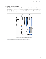
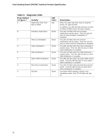
Intel Desktop Board DP67BG Technical Product Specification Table 9. Diagnostic LEDs Item/Callout in Figure 7 Activity A Watch Dog Timer Fire/ Back to BIOS LED Color Red B Processor Initialization Green C Memory Initialization Green D Video Initialization Green E USB Initialization Green F Option ROM Initialization Green G Hard Drive Initialization Green H OS Start Green Description When the watch dog timer fires to reset the board, this LED will flash. In addition, this LED will light and stay on when the Back to BIOS button has been pressed. This LED will flash when the processor initialization activity starts. Then the LED will stay on when processor initialization is complete. This LED will flash when the memory initialization activity starts. Then the LED will stay on when memory initialization is complete. This LED will flash when the video initialization activity starts. Then the LED will stay on when video initialization is complete. This LED will flash when the USB initialization activity starts. Then the LED will stay on when USB initialization is complete. This LED will flash when the option ROM activity starts. Then the LED will stay on when option ROM initialization is complete. This LED will flash when the hard drive activity starts. Then the LED will stay on when hard drive initialization is complete. Just before BIOS transfers control to the operating system, this LED will light and stay on. 36
-
 1
1 -
2
-
3
-
4
-
5
-
6
-
7
-
8
-
9
-
10
-
11
-
12
-
13
-
14
-
15
-
16
-
17
-
18
-
19
-
20
-
21
-
22
-
23
-
24
-
25
-
26
-
27
-
28
-
29
-
30
-
 31
31 -
 32
32 -
 33
33 -
 34
34 -
 35
35 -
 36
36 -
 37
37 -
 38
38 -
 39
39 -
 40
40 -
 41
41 -
42
-
43
-
44
-
45
-
46
-
47
-
48
-
49
-
50
-
51
-
52
-
53
-
54
-
55
-
56
-
57
-
58
-
59
-
60
-
61
-
62
-
63
-
64
-
65
-
66
-
67
-
68
-
69
-
70
-
71
-
72
-
73
-
74
-
75
-
76
-
77
-
78
-
79
-
80
-
81
-
82
-
83
-
84
-
85
-
86
-
87
-
88
-
89
-
90
-
91
 |
 |