Intel DP67BG Product Specification - Page 12
Table 2., Components Shown - no post
 |
View all Intel DP67BG manuals
Add to My Manuals
Save this manual to your list of manuals |
Page 12 highlights
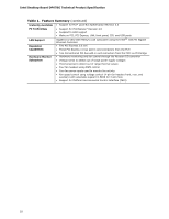
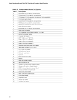
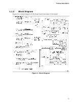
Intel Desktop Board DP67BG Technical Product Specification Table 2. Components Shown in Figure 1 Label Description A PCI Express x1 bus add-in card connector B Conventional PCI bus add-in card connector C PCI Express 2.0 x16 connector (x8 electrical; x16 compatible) D Front panel audio header E Conventional PCI bus add-in card connector F PCI Express x1 bus add-in card connector G PCI Express 2.0 x16 bus add-in card connector H Rear chassis fan header I PCI Express x1 bus add-in card connector J Back panel connectors K 12 V processor core voltage connector (2 x 4 pin) L LGA1155 processor socket M Processor fan header N DIMM 3 (Channel A DIMM 0) O DIMM 1 (Channel A DIMM 1) P DIMM 4 (Channel B DIMM 0) Q DIMM 2 (Channel B DIMM 1) R Alternate front panel power LED header S Main power connector (2 x 12 pin) T POST code LED display U Onboard power button V Onboard reset button W Speaker X Front chassis fan header Y Battery Z Intel P67 Express Chipset AA SATA connectors (6) BB Consumer IR transmitter (output) header CC Consumer IR receiver (input) header DD BIOS Setup configuration jumper block EE Front panel USB 2.0 headers (3) FF Chassis intrusion header GG IEEE 1394a front panel header HH Front panel header II Diagnostic LEDs JJ S/PDIF out header KK Auxiliary fan header 12
-
 1
1 -
2
-
3
-
4
-
5
-
6
-
 7
7 -
 8
8 -
 9
9 -
 10
10 -
 11
11 -
 12
12 -
 13
13 -
 14
14 -
 15
15 -
 16
16 -
 17
17 -
18
-
19
-
20
-
21
-
22
-
23
-
24
-
25
-
26
-
27
-
28
-
29
-
30
-
31
-
32
-
33
-
34
-
35
-
36
-
37
-
38
-
39
-
40
-
41
-
42
-
43
-
44
-
45
-
46
-
47
-
48
-
49
-
50
-
51
-
52
-
53
-
54
-
55
-
56
-
57
-
58
-
59
-
60
-
61
-
62
-
63
-
64
-
65
-
66
-
67
-
68
-
69
-
70
-
71
-
72
-
73
-
74
-
75
-
76
-
77
-
78
-
79
-
80
-
81
-
82
-
83
-
84
-
85
-
86
-
87
-
88
-
89
-
90
-
91
 |
 |