Intel S5500BCR Service Guide - Page 21
Hardware Requirements - cpu
 |
View all Intel S5500BCR manuals
Add to My Manuals
Save this manual to your list of manuals |
Page 21 highlights
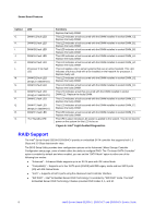
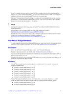
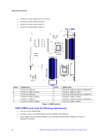
Server Board Features If RAID 5 is needed, you must install the optional Intel® RAID Activation Key AXXRAKSW5 accessory. This activation key is placed on the SATA_ RAID_5_Key connector located on the left side of the server board. For installation instructions, see the documentation included with the activation key. When Intel® Embedded Server RAID Technology II is enabled with the embedded SATA controller, enclosure management is provided through the SATA_SGPIO connector on the server board when a cable is attached between this connector and the backplane or I2C interface. / NOTE For help with navigating the BIOS Setup utility, see the Intel® Server Board S5520HC/S5500HCV Technical Product Specification. For information on how to configure RAID, refer to the RAID software user's guide at: http://www.intel.com/support/motherboards/server/S5520HC/howto.htm For help with enclosure management cabling, refer to the Enclosure Management Cabling Guide for Pedestal Systems with hot-swap Drive Backplanes. This guide is available at: http://support.intel.com/support/motherboards/server/S5520HC/compat.htm Hardware Requirements To avoid integration difficulties and possible board damage, your system must meet the following requirements outlined. For a list of qualified components, see the links under "Additional Information and Software". Processor One or two Intel® Xeon® Processor 5500 series or Intel® Xeon® Processor 5600 series For a list of supported processors, see the links under "Additional Information and Software". You must populate processors in sequential order. Therefore, you must populate Processor Socket 1 (CPU 1) before processor socket 2 (CPU 2). For optimum performance, when two processors are installed, both must be the identical revision and have the same core voltage and Intel® QPI/Core speed. Memory The Intel® Server Board S5520HC/S5520HCT provides 12 DIMM sockets in six channels. Each channel contains two DIMM sockets: „ Channel A contains DIMM sockets A1 and A2 „ Channel B contains DIMM sockets B1 and B2 „ Channel C contains DIMM sockets C1 and C2 „ Channel D contains DIMM sockets D1 and D2 „ Channel E contains DIMM sockets E1 and E2 „ Channel F contains DIMM sockets F1 and F2 The Intel® Server Board S5520HCV provides nine DIMM sockets in six channels. Channels A, B, and C contain two DIMM sockets per channel. Channels D, E, and F contain one DIMM socket per channel: „ Channel A contains DIMM sockets A1 and A2 „ Channel B contains DIMM sockets B1 and B2 Intel® Server Board S5520HC, S5520HCT and S5500HCV Service Guide 9
-
 1
1 -
2
-
3
-
4
-
5
-
6
-
7
-
8
-
9
-
10
-
11
-
12
-
13
-
14
-
15
-
 16
16 -
 17
17 -
 18
18 -
 19
19 -
 20
20 -
 21
21 -
 22
22 -
 23
23 -
 24
24 -
 25
25 -
 26
26 -
27
-
28
-
29
-
30
-
31
-
32
-
33
-
34
-
35
-
36
-
37
-
38
-
39
-
40
-
41
-
42
-
43
-
44
-
45
-
46
-
47
-
48
-
49
-
50
-
51
-
52
-
53
-
54
-
55
-
56
-
57
-
58
-
59
-
60
-
61
-
62
-
63
-
64
-
65
-
66
 |
 |
