Intel S815EBM1 Product Guide
Intel S815EBM1 - Server Board Motherboard Manual
 |
UPC - 735858149839
View all Intel S815EBM1 manuals
Add to My Manuals
Save this manual to your list of manuals |
Intel S815EBM1 manual content summary:
- Intel S815EBM1 | Product Guide - Page 1
Intel® Server Board S815EBM1 Product Guide A Guide for Technically Qualified Assemblers of Intel® Identified Subassemblies/Products Order Number: A67054-003 1 - Intel S815EBM1 | Product Guide - Page 2
a particular purpose. Intel assumes no responsibility for any errors that may appear in this document. Intel makes no commitment to update nor to keep exchanges date data with it. Intel, Pentium, and Celeron are the trademarks or registered trademarks of Intel Corporation or its subsidiaries in the - Intel S815EBM1 | Product Guide - Page 3
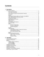
Panel Connectors 9 Server Board Connector and Component Locations 10 Processors ...11 Memory ...11 Intel® 82815E Graphics Memory Controller Hub (GMCH 12 Intel® 82801BA I/O Controller Hub (ICH2 13 Firmware Hub (FWH 13 Input/Output (I/O) Controller 13 Real-Time Clock ...13 USB Support...13 PCI - Intel S815EBM1 | Product Guide - Page 4
Menu...58 Boot Device Priority Submenu 59 Hard Disk Drives Submenu 60 Removable Devices Submenu 60 ATAPI CDROM Drives Submenu 61 Exit Menu ...62 4 Solving BIOS Problems BIOS Beep Codes ...63 BIOS Error Messages ...64 iv Intel Server Board S815EBM1 Product Guide - Intel S815EBM1 | Product Guide - Page 5
Connectors 68 Add-In Board and Peripheral Interface Connectors 69 Server Board Resources ...70 Memory Map ...70 DMA Channels 14. Attaching the Fan to the Fan Heatsink 29 15. Connecting the Processor Fan Cable to the Processor Fan Connector ...29 16. Removing the Fan Heatsink 30 17. Removing the - Intel S815EBM1 | Product Guide - Page 6
. Hard Disk Drives Submenu 60 26. Removable Devices Submenu 60 27. ATAPI CDROM Drives Submenu 61 28. Exit Menu...62 29. Beep Codes ...63 30. BIOS Error Messages 64 31. System Memory Map 70 32. DMA Channels...70 33. I/O Map...71 34. Interrupts ...72 vi Intel Server Board S815EBM1 Product Guide - Intel S815EBM1 | Product Guide - Page 7
Description Server Board Features Table 1. Server Board Features Feature Processors Memory Chipset I/O Control Peripheral Interfaces SCSI LED Connector Expansion Capabilities BIOS Power Management Wake on LAN† Technology Form Factor Description Support for either an Intel® Pentium® III processor - Intel S815EBM1 | Product Guide - Page 8
port 3 E. Parallel port, burgundy F. VGA port, blue G. Serial port A, teal H. RJ-45 LAN connector with LED display I. USB port 0 J. USB port 2 Figure 1. Back Panel Connectors 8 Intel Server Board S815EBM1 Product Guide - Intel S815EBM1 | Product Guide - Page 9
Front Panel Connectors Figure 2 shows the location of the front panel connectors. 31 A J9H4 B CD 15 1 16 2 I HG F E 15 1 16 J9H3 2 A. Chassis intrusion connector B. Reserved C. Reset switch D. Hard drive activity LED E. Power LED F. On/Off switch G. No connect H. Ground I. +5 V Figure - Intel S815EBM1 | Product Guide - Page 10
fan (fan 3) U. BIOS configuration jumper block J. Floppy drive connector K. Primary IDE connector V. Wake on LAN technology connector W. 4 Mbit Firmware Hub (FWH) L. Secondary IDE connector X. PCI expansion slots Figure 3. Server Board Components 10 Intel Server Board S815EBM1 Product Guide - Intel S815EBM1 | Product Guide - Page 11
by product s-spec. For the latest information on processor support for the boards, refer to the Intel server board web site at: http://support.intel.com/support/motherboards/server/S815EBM1/ For instructions on installing or upgrading the processor, see Chapter 2. Memory The board supports 168-pin - Intel S815EBM1 | Product Guide - Page 12
MB at 100 MHz. Intel® 82815E Graphics Memory Controller Hub (GMCH) The GMCH provides the following: • An integrated Synchronous DRAM memory controller with autodetection of SDRAM. • Support for ACPI Rev 2.0 and APM Rev 1.2 compliant power management. 12 Intel Server Board S815EBM1 Product Guide - Intel S815EBM1 | Product Guide - Page 13
four USB peripheral devices directly to the server without an external hub. To attach more than four devices, connect an external hub to either of the built-in ports. The server board supports the UHCI specification and takes advantage of standard software drivers written to be compatible with UHCI - Intel S815EBM1 | Product Guide - Page 14
server. The interface supports: • Up to four IDE devices (such as hard drives) • PIO Mode 3 and PIO Mode 4 devices • Ultra UDMA/33, Ultra ATA/66, and Ultra ATA/100 protocols • Support for laser servo (LS-120) drives Expansion Slots The S815EBM1 board has three add-in board connectors. BIOS The BIOS - Intel S815EBM1 | Product Guide - Page 15
Power Management (APM) support • Programmable transit threshold LAN Subsystem Software For Intel 82562ET Fast Ethernet WfM PCI LAN software and drivers, refer to the S815EBM1, link on Intel's support web site at: http://support.intel.com/support/motherboards/server/S815EBM1/ Description 15 - Intel S815EBM1 | Product Guide - Page 16
A battery on the server board keeps the values in CMOS RAM and the clock current when the server is turned off. See Chapter 2 for instructions on how to replace the battery. Power Management Features Power management is implemented at several levels, including: • Software support: Advanced Power - Intel S815EBM1 | Product Guide - Page 17
and/or USB buses exceeds power supply capacity, the server board may lose register settings stored in memory, etc. Wake on Ring The operation of Wake on Ring can be summarized as follows: • Powers up the server from the APM soft-off mode. • Modem must support PME. • Requires two calls to access the - Intel S815EBM1 | Product Guide - Page 18
18 Intel Server Board S815EBM1 Product Guide - Intel S815EBM1 | Product Guide - Page 19
Only a technically qualified person should configure the server board. WARNING Hazardous conditions, devices & cables: Hazardous Gripping the wide sides can damage the contacts inside the jumper, causing intermittent problems with the function controlled by that jumper. Take care to grip with, but - Intel S815EBM1 | Product Guide - Page 20
/memory/ Installing DIMMs To install DIMMs, follow these steps: 1. Observe the safety and ESD precautions at the beginning of this chapter. 2. Turn off all peripheral devices connected to the server. Turn off the server and disconnect the AC power cord. 20 Intel Server Board S815EBM1 Product Guide - Intel S815EBM1 | Product Guide - Page 21
down on the top edge of the DIMM until the retaining clips snap into place. Make sure the clips are firmly in place. 9. Replace the server's cover and reconnect the AC power cord. Removing DIMMs To remove a DIMM, follow these steps: 1. Observe the safety and ESD precautions at the beginning of - Intel S815EBM1 | Product Guide - Page 22
correct airflow within the chassis. Install the I/O shield before installing the server board in the chassis. Place the shield inside the chassis and press the shield [81.768] 5.010 [127.25] Pictorial View Figure 5. I/O Shield Dimensions OM12390 22 Intel Server Board S815EBM1 Product Guide - Intel S815EBM1 | Product Guide - Page 23
Installing the Server Board Refer to your chassis manual for instructions on installing the server board. Six screws secure the server board to the chassis. Figure 6 shows the locations of the mounting screw holes. ✏ NOTES You will need a Phillips (#2 bit) screwdriver. Refer to Page 73 for - Intel S815EBM1 | Product Guide - Page 24
7, B). 3. Aligning the pins of the processor with the socket, insert the processor into the socket (see Figure 7, A and C). 4. Close the handle completely (see Figure 7, D). B C A D OM11065 Figure 7. Installing the Processor in the Processor Socket 24 Intel Server Board S815EBM1 Product Guide - Intel S815EBM1 | Product Guide - Page 25
Place the fan heatsink on top of the processor (see Figure 8). 2/)!% OM09415 Figure 8. Attaching the Heatsink to the Processor 6. Attach the fan heatsink clips to the processor socket (see Figure 9). A B OM09416 A. Fan Heatsink Clip B. Processor Socket Figure 9. Attaching the Fan Heatsink Clips to - Intel S815EBM1 | Product Guide - Page 26
instructions: 1. Observe the safety and ESD precautions at the beginning of this chapter. 2. Disconnect the processor fan cable. 3. Detach the fan heatsink clips. 4. Remove the heatsink. 5. Raise the socket handle completely. 6. Remove the processor. 26 Intel Server Board S815EBM1 Product Guide - Intel S815EBM1 | Product Guide - Page 27
and will void this server board warranty. For more details on processors specifically supported with this board and the included thermal solution please refer to: http://support.intel.com/support/motherboards/server/S815EBM1/ To install a 1 GHz processor, follow the instructions given on page 24 - Intel S815EBM1 | Product Guide - Page 28
click into place. Hold the clip handle (see Figure 13, A) and very slowly lower the handle until the clip secures the fan heatsink to the processor socket. A B OM11062 Figure 13. Lowering the Plastic Clip Handle 28 Intel Server Board S815EBM1 Product Guide - Intel S815EBM1 | Product Guide - Page 29
heatsink (B) as illustrated in Figure 14. A B C OM11061 Figure 14. Attaching the Fan to the Fan Heatsink 5. Connect the processor fan cable to the processor fan connector (see Figure 15). J1B1 J1B1 OM11175 Figure 15. Connecting the Processor Fan Cable to the Processor Fan Connector Upgrading 29 - Intel S815EBM1 | Product Guide - Page 30
Processor To remove the 1 GHz processor, follow these instructions: 1. Observe the safety and ESD precautions at the beginning of this chapter. 2. Disconnect the processor . 7. Raise the processor socket handle completely. 8. Remove the processor. 30 Intel Server Board S815EBM1 Product Guide - Intel S815EBM1 | Product Guide - Page 31
. The location of the server board battery is shown in Figure 17 on page 33. The battery should last about seven years whereupon it begins to lose voltage. When the voltage drops below a certain level, the BIOS Setup program settings stored in CMOS RAM (for example, the date and time) might not be - Intel S815EBM1 | Product Guide - Page 32
devem ser recicladas nos locais apropriados. A eliminação de baterias usadas deve ser feita de acordo com as regulamentações ambientais da região. (Brazilian Portuguese) 32 Intel Server Board S815EBM1 Product Guide - Intel S815EBM1 | Product Guide - Page 33
of this chapter. 2. Turn off all peripheral devices connected to the server. Disconnect the server's power cord from the AC power source (wall outlet or power adapter). 3. Remove the server cover. 4. Locate the battery on the board (see Figure 17). 5. With your fingertip, gently pull back the tab - Intel S815EBM1 | Product Guide - Page 34
IDE Cable The Intel® boxed server board package includes a 40-contact, 80-conductor IDE cable. It is capable of connecting two drives to the server board. The cable supports Ultra ATA/66 connector (P3). B A Figure 18. Connecting the IDE Cable OM12205 34 Intel Server Board S815EBM1 Product Guide - Intel S815EBM1 | Product Guide - Page 35
jumper with the power on may result in unreliable server operation. 31 J9G2 Figure 19. BIOS Configuration Jumper Block Location OM12206 This three-pin jumper block, shown in Figure 19, enables all server board configurations to be done in BIOS Setup. Table 5 shows the jumper settings for the - Intel S815EBM1 | Product Guide - Page 36
Press to save the current values and exit Setup. 10. Turn off the server. Disconnect the server's power cord from the AC power source. 11. Remove the server cover. 12. To restore normal operation, place the jumper on pins 1-2 as shown below. 3 1 36 Intel Server Board S815EBM1 Product Guide - Intel S815EBM1 | Product Guide - Page 37
installation wizards. To update the BIOS with the Intel Express BIOS Update utility: 1. Go to the Intel support web site: http://support.intel.com/support/motherboards/server 2. Navigate to the S815EBM1 page and click the Express BIOS Update utility file for the board's BIOS. 3. Download the file - Intel S815EBM1 | Product Guide - Page 38
World Wide Web site: http://support.intel.com/support/motherboards/server/ ✏ NOTE Review the instructions distributed with the update utility before attempting a BIOS update. The Intel Flash Memory Update Utility allows you to: • Update the BIOS in flash memory • Update the language section of the - Intel S815EBM1 | Product Guide - Page 39
Follow the directions in the README.TXT file. Creating a BIOS Update Media 1. Obtain the BIOS update file through your server supplier or from the Intel World Wide Web site: http://support.intel.com/support/motherboards/server/ 2. Copy the BIOS update file to a temporary directory on your hard disk - Intel S815EBM1 | Product Guide - Page 40
press . 7. To accept the defaults, press . 8. In Setup, enter the settings you wrote down before beginning the BIOS upgrade. 9. To save the settings, press . 10. To accept the settings, press . 11. Turn off the server and reboot. 40 Intel Server Board S815EBM1 Product Guide - Intel S815EBM1 | Product Guide - Page 41
1 4. Insert the bootable BIOS update diskette into diskette drive A. 5. Replace the server cover, connect the power cord, turn on the server, and allow it to A activity ceases (temporarily) indicating the successful recovery of the BIOS core. Drive A activity will begin again followed by two more - Intel S815EBM1 | Product Guide - Page 42
management features Selects boot options and power supply controls Saves or discards changes to Setup program options * For information about the BIS, refer to the Intel Web site at: http://developer.intel.com/design/security/index1.htm 42 Intel Server Board S815EBM1 Product Guide - Intel S815EBM1 | Product Guide - Page 43
BIOS Setup program Exits the menu Maintenance Menu This menu is used to clear passwords, to access the extended configuration submenu, and to access processor information Service (BIS) credentials. Invokes the Extended Configuration submenu. Displays CPU Information. Displays CPU's Microcode Update - Intel S815EBM1 | Product Guide - Page 44
to auto or user defined. Selects the number of clock cycles required to address a column in memory. Selects the number of clock cycles between addressing a row and addressing a column. Selects the length of time required before accessing a new row. 44 Intel Server Board S815EBM1 Product Guide - Intel S815EBM1 | Product Guide - Page 45
only when a Pentium III processor is installed.) Specifies the current time. Specifies the current date. ✏ NOTE Additional language support available. For more information visit Intel's support web site at: www.support.intel.com/support/motherboards/server/S815EBM1. Configuration Software and - Intel S815EBM1 | Product Guide - Page 46
. Specifies type of connected IDE device. When selected, displays the Diskette Configuration submenu. Configures Event Logging. When selected, displays the Event Log Configuration submenu. 46 Intel Server Board S815EBM1 Product Guide - Intel S815EBM1 | Product Guide - Page 47
PCI Configuration Submenu To access this submenu, select Advanced on the menu bar, then PCI Configuration. Maintenance Main Advanced Security Power PCI Configuration Boot Configuration Peripheral Configuration IDE Configuration Diskette Configuration Event Log Configuration Boot Exit The - Intel S815EBM1 | Product Guide - Page 48
if manual configuration is desired. No lets the BIOS memory on the next boot. Yes clears the PCI/PnP configuration data stored in flash memory on the next boot. Specifies the power-on state of the Numlock feature on the numeric keypad of the keyboard. 48 Intel Server Board S815EBM1 Product Guide - Intel S815EBM1 | Product Guide - Page 49
IDE Configuration Diskette Configuration Event Log Configuration Boot Exit The submenu represented in Table 14 is used for configuring server peripherals. Table 14. Peripheral Configuration Submenu Feature Serial Port A Options • Disabled • Enabled • Auto Base I/O Address (This feature is - Intel S815EBM1 | Product Guide - Page 50
Disabled • Enabled Enables or disables the LAN device. Enables or disables USB legacy support. (See USB Support on page 13 for more information. IDE Configuration Submenu To access this submenu, . Specifies the hard disk drive pre-delay. continued 50 Intel Server Board S815EBM1 Product Guide - Intel S815EBM1 | Product Guide - Page 51
Table 15. IDE Configuration Submenu (continued) Primary IDE Master No options Reports type of connected IDE device. When selected, displays the Primary IDE Master submenu. Primary IDE Slave No options Reports type of connected IDE device. When selected, displays the Primary IDE Slave submenu. - Intel S815EBM1 | Product Guide - Page 52
number of sectors per block for transfers from the hard disk drive to memory. Check the hard disk drive's specifications for optimum setting. Specifies the PIO mode. Specifies the Ultra DMA mode options appear only if an IDE device is installed. 52 Intel Server Board S815EBM1 Product Guide - Intel S815EBM1 | Product Guide - Page 53
Diskette Configuration Submenu To access this menu, select Advanced on the menu bar, then Diskette Configuration. Maintenance Main Advanced Security Power PCI Configuration Boot Configuration Peripheral Configuration IDE Configuration Diskette Configuration Event Log Configuration Boot Exit - Intel S815EBM1 | Product Guide - Page 54
the event log are valid. Displays the event log. Clears the event log after rebooting. Enables logging of events. Marks all events as read. 54 Intel Server Board S815EBM1 Product Guide - Intel S815EBM1 | Product Guide - Page 55
• No User Access Level (Note 2) • Limited • No Access Sets BIOS Setup Utility access rights for user level. • View Only • Full Unattended and a supervisor password have been set. 3. If both Legacy USB Support (in the Peripheral Configuration submenu) and Unattended Start (in the Security - Intel S815EBM1 | Product Guide - Page 56
of operation if an AC power loss occurs. Power On restores power to the server. Stay Off keeps the power off until the power button is pressed. Last only, specifies how the server responds to an incoming call on an installed modem when the power is off. 56 Intel Server Board S815EBM1 Product Guide - Intel S815EBM1 | Product Guide - Page 57
• 20 Minutes • 30 Minutes • 60 Minutes • 120 Minutes • Disabled • Enabled Description Enables or disables the BIOS power management feature. Specifies the amount of time before the server enters standby mode. Enables power management for hard disks during standby modes. ACPI Submenu To access this - Intel S815EBM1 | Product Guide - Page 58
messages. Enables the computer to boot without running certain POST tests. Enables the BIOS to scan the flash memory for user binary files that are executed at boot time. Specifies the boot sequence boot sequence from the available ATAPI CD-ROM drives. 58 Intel Server Board S815EBM1 Product Guide - Intel S815EBM1 | Product Guide - Page 59
in this list will reflect as many boot entry vector (BEV) boot devices (for example, Intel UNDI, PXE devices) and SCSI CD-ROM drives as are installed, up to the five BEV boot devices supported by the BIOS. 2. While the predefined boot device types are listed individually in submenus by type, the BEV - Intel S815EBM1 | Product Guide - Page 60
display up to twelve hard disk drives, the maximum number of hard disk drives supported by the BIOS. Removable Devices Submenu To access this menu, select Boot on the menu bar, devices, the maximum number of removable devices supported by the BIOS. 60 Intel Server Board S815EBM1 Product Guide - Intel S815EBM1 | Product Guide - Page 61
one boot device of this type is installed. This list will display up to four ATAPI CDROM drives, the maximum number of ATAPI CDROM drives supported by the BIOS. Configuration Software and Utilities 61 - Intel S815EBM1 | Product Guide - Page 62
this memory is corrupted, the BIOS reads the custom defaults. If no custom defaults are set, the BIOS reads the factory defaults. Discard Changes Discards changes without exiting Setup. The option values present when the server was turned on are used. 62 Intel Server Board S815EBM1 Product Guide - Intel S815EBM1 | Product Guide - Page 63
be reset First 64 K memory failure Timer not operational Processor failure (Reserved; not used) 8042 GateA20 cannot be toggled (memory failure or not present) Exception interrupt error Display memory R/W error (Reserved; not used) CMOS Shutdown register test error Invalid BIOS (such as, POST module - Intel S815EBM1 | Product Guide - Page 64
invalid and has been updated. Updated Failed NVRAM was invalid but was unable to be updated. Keyboard Error Error in the keyboard connection. Make sure keyboard is connected properly. KB/Interface Error Keyboard interface test failed. continued 64 Intel Server Board S815EBM1 Product Guide - Intel S815EBM1 | Product Guide - Page 65
. BIOS Error Messages (continued) Error Message Explanation Memory Size Decreased Memory size has decreased since the last boot. If no memory was removed, then memory may be bad. Memory Size Increased Memory size has increased since the last boot. If no memory was added, there may be a problem - Intel S815EBM1 | Product Guide - Page 66
66 Intel Server Board S815EBM1 Product Guide - Intel S815EBM1 | Product Guide - Page 67
chassis. A fault in the load presented by the external devices could cause damage to the server, the interconnecting cable, and the external devices themselves. The server board connectors can be divided into three groups, as shown in Figure 20. A A Back panel connectors (see page 8) B Baseboard - Intel S815EBM1 | Product Guide - Page 68
Control Connectors Figure 21 shows the power and hardware connectors. A 1 1 1 1 10 11 20 D C B OM12209 A. Processor fan (fan 1) B. Power C. Chassis fan (fan 2) D. Wake on LAN technology Figure 21. Power and Hardware Control Connectors 68 Intel Server Board S815EBM1 Product Guide - Intel S815EBM1 | Product Guide - Page 69
Figure 22 shows the add-in board and peripheral interface connectors. A BC 40 2 1 39 2 40 1 39 2 34 1 33 FE D OM12210 A. PCI slot 3 B. PCI slot 2 C. PCI slot 1 D. Diskette drive E. Primary IDE F. Secondary IDE Figure 22. Add-in Board and Peripheral Interface Connectors Technical - Intel S815EBM1 | Product Guide - Page 70
memory Runtime BIOS Reserved Available high DOS memory (open to the PCI bus) Video memory and BIOS Extended BIOS data (movable by memory manager software) Extended conventional memory Conventional memory (for ECP or EPP) DMA controller Open Open Open 70 Intel Server Board S815EBM1 Product Guide - Intel S815EBM1 | Product Guide - Page 71
CMOS DMA controller Fast A20 and PIC PIC APM control DMA Numeric data processor Secondary IDE channel Primary IDE channel LPT3 LPT2 COM4 / video (8514A IDE channel command port Secondary IDE channel status port LPT1 Intel 82815E GMCH / AGP Intel 82815E GMCH / AGP COM3 Diskette channel 1 Primary IDE - Intel S815EBM1 | Product Guide - Page 72
14 Primary IDE (if present, else user available) 15 Secondary IDE (if present, else user available) * Default, but can be changed to another IRQ. 72 Intel Server Board S815EBM1 Product Guide - Intel S815EBM1 | Product Guide - Page 73
) Product EMC Compliance The S815EBM1 has been has been tested and verified to comply with the following electromagnetic compatibility (EMC) regulations when installed a compatible Intel host system. For information on compatible host system(s) refer to Intel's Server Builder website or contact your - Intel S815EBM1 | Product Guide - Page 74
) A44507-xxx. Also includes SKU number starting with AA followed by additional alphanumeric characters. • Battery "+ Side Up" marking: located on the component side of the board in close proximity to the battery holder. • Mic mark 74 Intel Server Board S815EBM1 Product Guide - Intel S815EBM1 | Product Guide - Page 75
and test the server board, observe all warnings and cautions in the installation instructions. To avoid injury, be careful of: • Sharp pins on connectors • Sharp pins on printed circuit assemblies • Rough edges and sharp corners on the chassis • Hot components (like processors, voltage regulators - Intel S815EBM1 | Product Guide - Page 76
output circuits. Place Battery Marking There is insufficient space on this server board to provide instructions for replacing and disposing of the battery. For system safety certification, systems, test equipment, etc.) may require further evaluation. 76 Intel Server Board S815EBM1 Product Guide
-
 1
1 -
 2
2 -
 3
3 -
 4
4 -
 5
5 -
 6
6 -
 7
7 -
8
-
9
-
10
-
11
-
12
-
13
-
14
-
15
-
16
-
17
-
18
-
19
-
20
-
21
-
22
-
23
-
24
-
25
-
26
-
27
-
28
-
29
-
30
-
31
-
32
-
33
-
34
-
35
-
36
-
37
-
38
-
39
-
40
-
41
-
42
-
43
-
44
-
45
-
46
-
47
-
48
-
49
-
50
-
51
-
52
-
53
-
54
-
55
-
56
-
57
-
58
-
59
-
60
-
61
-
62
-
63
-
64
-
65
-
66
-
67
-
68
-
69
-
70
-
71
-
72
-
73
-
74
-
75
-
76
 |
 |

1
Intel
®
Server Board S815EBM1
Product Guide
A Guide for Technically Qualified Assemblers of Intel
®
Identified
Subassemblies/Products
Order Number:
A67054-003