Invacare 4V66FLR Owners Manual
Invacare 4V66FLR Manual
 |
View all Invacare 4V66FLR manuals
Add to My Manuals
Save this manual to your list of manuals |
Invacare 4V66FLR manual content summary:
- Invacare 4V66FLR | Owners Manual - Page 1
2. Size A5 3. Orientation: Landscape 4. Color: Black and White 5. Special Instructions: DO NOT PRINT THIS DRAWING. This drawing is for informational purposes only. See attached document. 5/29/14 TITLE: Veranda 3000/4000 User Manual PART NUMBER: 1567855 REV: SHEET: C 1 OF 1 ALL DIMENSIONS ARE - Invacare 4V66FLR | Owners Manual - Page 2
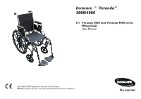
Invacare ® Veranda™ 3000/4000 EN Veranda 3000 and Veranda 4000 series Wheelchair User Manual This manual MUST be given to the user of the product. BEFORE using this product, read this manual and save for future reference. - Invacare 4V66FLR | Owners Manual - Page 3
©2014 Invacare®Corporation All rights reserved. Republication, duplication or modification in whole or in part is prohibited without prior written permission from Invacare. Trademarks are identified by ™and ®. All trademarks are owned by or licensed to Invacare Corporation or its subsidiaries unless - Invacare 4V66FLR | Owners Manual - Page 4
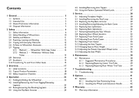
Anti-Tippers 25 4.6 Using the Patient Operated Wheel Locks 27 5 Service 28 5.1 Adjusting Footplate Height 28 5.2 Installing/Removing the Heel Loop 6.1.3 Replacing/Repairing Rear Wheel Tire/Tube 39 7 Troubleshooting 40 7.1 Troubleshooting 40 8 Options 41 8.1 Options 41 8.1.1 Installing - Invacare 4V66FLR | Owners Manual - Page 5
9.2 Usability Survey 45 - Invacare 4V66FLR | Owners Manual - Page 6
result in damage to property if it is not avoided. Gives useful tips, recommendations and information for efficient, trouble-free use. General 1.2 Intended Use The intended use for the manual (mechanical) wheelchair is to provide mobility to persons who may be restricted to a sitting position. The - Invacare 4V66FLR | Owners Manual - Page 7
use this product or any available optional equipment without first completely reading and understanding these instructions and any additional instructional material such as owner's manuals, service manuals or instruction sheets supplied with this product or optional equipment. If you are unable to - Invacare 4V66FLR | Owners Manual - Page 8
of the wheelchair. Seat Depth Caster Size Caster P osition Wheel Size Wheel Position Anti-tippers User Condi tion WARNING! Repair and Service Information - Unless otherwise noted, all service and adjustments should be performed while the wheelchair is unoccupied. - After ANY adjustments, repair or - Invacare 4V66FLR | Owners Manual - Page 9
Invacare ® Veranda™ 3000/4000 WARNING! Operating Information - To determine and establish your particular safety limits, practice bending, reaching and transferring activities in several combinations in the presence of a qualified healthcare professional before attempting active use of the - Invacare 4V66FLR | Owners Manual - Page 10
the anti-tippers as an additional safeguard for the wheelchair user. - Invacare strongly recommends that anti-tippers be used at all times. - The manual wheelchair is intended for indoor and outdoor use on firm surfaces. When outdoors on wet, soft ground or on gravel surfaces, anti-tippers may not - Invacare 4V66FLR | Owners Manual - Page 11
the close attention of the wheelchair user as well as the assistant. This manual points out the most common procedures and techniques involved in the safe operation architectural barriers. Use this information only as a "basic" guide. The techniques that are discussed on the following pages have - Invacare 4V66FLR | Owners Manual - Page 12
point for the new wheelchair user and assistant with "safety" as the most important consideration for all. 2.3 Stability and Balance WARNING! - DO NOT attempt to lift a wheelchair by lifting on any removable (detachable) parts. Lifting by means of any removable (detachable) parts of the wheelchair - Invacare 4V66FLR | Owners Manual - Page 13
Invacare ® Veranda™ 3000/4000 change to the normal balance, the center of gravity, and the weight distribution of the wheelchair. To determine and establish your particular safety limits, practice bending, reaching and transferring activities in several combinations in the presence of a qualified - Invacare 4V66FLR | Owners Manual - Page 14
damage to the wheelchair. Also, be aware of any removable (detachable) parts. These MUST NEVER be used to move the wheelchair or as lifting supports, as they may be inadvertently released, resulting in possible injury to the user and/or assistant(s). When learning a new assistance technique, have an - Invacare 4V66FLR | Owners Manual - Page 15
moving. Invacare recommends using two assistants and making thorough preparations. Make sure to use only secure, non-detachable parts for hand-held supports. - 9000 XT recliner only - ALWAYS return the back to the upright position before lifting the wheelchair. Follow this procedure for moving the - Invacare 4V66FLR | Owners Manual - Page 16
Moving Down Stairs 1. If necessary, rotate the anti-tippers so the wheels are facing up. 2. One assistant (positioned behind the wheelchair), securely grasps a non-removable (non-detachable) part of the wheelchair for leverage and tilts the wheelchair back to the balance point. 3. After the - Invacare 4V66FLR | Owners Manual - Page 17
Invacare ® Veranda™ 3000/4000 Position the wheelchair as close as possible along side the seat to which you are transferring, with the front casters parallel to it. Remove the armrest, if installed. Engage wheel locks. Shift body weight into seat with transfer. During independent transfer, little or - Invacare 4V66FLR | Owners Manual - Page 18
3 Overview 3.1 Label Locations Overview Crossmember Lower Frame Tube NOTE:On all adjustable anti-tippers Weight Capacity Label (part number 1111016) located here is used. WEIGHT CAPACITY: The wheelchair weight capactiy will be located on the Serial Number Label or on aWeight Capacity Label ( - Invacare 4V66FLR | Owners Manual - Page 19
17 inch Veranda 4000: 16, 17 or 18 inch, (tool free height adjustment) Back Angle: 90° 18 Elevating Legrest Angle: 104° to 180° Foot Support to Seat: 12-3/4 inches to 17-3/4 inches Armrest Height: 10-1/4 inches Rear Wheels: 24 inch Composite Corded Urethane Front Casters: 8 x 1-1/4 inch - Invacare 4V66FLR | Owners Manual - Page 20
Wheelchair Height: Wheelchair Depth: Veranda 4000: 34-1/2 to 38-5/8 inches Veranda 3000: 35-1/2 to 37-5/8 inches 31-7/8 to 33-1/5 inches (Without Front Riggings) Wheelchair Weight: Weight Limit: Veranda 4000: 33 pounds (Aprox.) 16 X 16 inch Seat, Without Front Riggings Veranda 3000: 34 pounds ( - Invacare 4V66FLR | Owners Manual - Page 21
Invacare ® Veranda™ 3000/4000 3.3 Safety Inspection Checklist Every six months, take your wheelchair to a qualified technician for a thorough inspection and servicing. Regular cleaning will reveal loose or worn parts and enhance the smooth operation of your wheelchair. To operate properly and safely - Invacare 4V66FLR | Owners Manual - Page 22
Inspect/Adjust Weekly q Ensure that the wheel locks prevent the wheelchair from moving when engaged. q Inspect tires and casters for flat spots, cracks or wear. Replace if necessary. q Inspect rear wheels for cracks in the rim or cracked or broken spokes. Replace if necessary. q Inspect axle - Invacare 4V66FLR | Owners Manual - Page 23
Invacare ® Veranda™ 3000/4000 4 Operation 4.1 Folding/Unfolding the Wheelchair Folding the Wheelchair 1. Swing footrest/legrest and calfpads in locked position to the front of the wheelchair. 2. Pivot footplates upward to vertical position. 3. With both hands, grasp the middle of the seat upholstery - Invacare 4V66FLR | Owners Manual - Page 24
Removing the Front Rigging/Eleveating Legrests WARNING! - After any adjustments, repair or service and before use, make sure all attaching hardware is tightened securely - otherwise pinch points. - The wheelchair user's leg MUST be supported by an assistant before attempting to lower legrest. 23 - Invacare 4V66FLR | Owners Manual - Page 25
Invacare ® Veranda™ 3000/4000 1. While supporting the elevating legrest A with one hand, rotate angle adjustment knob B counter clockwise with other hand. 2. Pull the adjustment knob up, then lift or lower elevating - Invacare 4V66FLR | Owners Manual - Page 26
-tippers are specific to the different seat-to-floor angles and/or seat-to-floor heights. Refer to the chart in this section of the manual for correct usage and adjustment. If these requirements cannot be achieved, DO NOT use the wheelchair. Contact a qualified technician. If changing the seat-to - Invacare 4V66FLR | Owners Manual - Page 27
Invacare ® Veranda™ 3000/4000 4. Measure the distance between the bottom of the anti-tipper wheels and the ground/floor. A 1 1/2 to 2 inch clearance between the bottom of the anti-tipper wheels and the ground/floor MUST be maintained at all times. 5. If the distance between the bottom of anti-tipper - Invacare 4V66FLR | Owners Manual - Page 28
4.6 Using the Patient Operated Wheel Locks WARNING! - DO NOT attempt to stop a moving wheelchair with wheel locks. Wheel locks are not brakes. - If the wheelchair is equipped with push to lock wheel locks, elevating legrests, and wheel lock extension handles, the wheel lock extension handles MUST be - Invacare 4V66FLR | Owners Manual - Page 29
Invacare ® Veranda™ 3000/4000 5 Service 5.1 Adjusting Footplate Height This procedure applies to the swingaway front riggings and swingaway elevating legrest. 1. Remove the threaded handle A and hex screw B securing the foot - Invacare 4V66FLR | Owners Manual - Page 30
and locknut, secure the EXISTING armrest and insert to the wheelchair frame. Securely tighten the hex screw and locknut. Service A B C Detail "A" G F D E H 5.4 Installing/Removing/Adjusting the Back Canes REMOVING THE BACK CANES - Reverse this procedure. ADJUSTING THE BACK CANE HEIGHT - Invacare 4V66FLR | Owners Manual - Page 31
Invacare ® Veranda™ 3000/4000 1. Insert the back cane A into the wheelchair frame B, aligning the mounting hole C in the back cane with one of three height settings D in the wheelchair frame. When securing the back cane to the wheelchair frame, ensure the head of the hex screw sets into the desired - Invacare 4V66FLR | Owners Manual - Page 32
. If replacing the same size rear wheel, note the mounting position on the wheelchair frame for proper reinstallation of the new rear wheel. Service 1. Remove the dust cap A, hex screw B, washer C, spacer (if installed) D and locknut E that secure the rear wheel F to the wheelchair frame G. The - Invacare 4V66FLR | Owners Manual - Page 33
Invacare ® Veranda™ 3000/4000 5.8 Replacing Rear Wheel Handrim WARNING! - If the wheelchair is equipped with permanent axles, this procedure MUST be performed by a qualified technician. 1. Remove the rear wheel A from the wheelchair. 5.7 Removing/Installing the Rear Wheels, page 31. 2. Remove the - Invacare 4V66FLR | Owners Manual - Page 34
Test wheelchair for maneuverability. 3. Readjust locknuts if necessary, and repeat STEPS 1-2 until correct. 4. Snap dust cover C over the locknut and stem. Service 5.11 Replacing Front Caster WARNING! - Make sure both casters are the same size before using the wheelchair, otherwise injury may occur - Invacare 4V66FLR | Owners Manual - Page 35
Invacare ® Veranda™ 3000/4000 5.12 Adjusting the Anti-Tippers A 1 1/2 to 2 inch clearance between the bottom of the anti-tipper wheels and the ground/floor MUST be maintained at all times. 1. Place the wheelchair on a flat surface. If adjusting anti-tippers on recliner models, ensure back canes are - Invacare 4V66FLR | Owners Manual - Page 36
TOP 24 inch TOP 18 1/2 MIDDLE 22 inch BOTTOM 19 1/2 BOTTOM 24 inch BOTTOM 1567855-C Rear W he e l Mount ing Posit ions Top Bottom Service 6 o r 8 Inch For k Mount ing Posit ions Top Middle Bottom 5.14 Adjusting the Patient Operated Wheel Locks WARNING! - DO NOT attempt to stop a moving - Invacare 4V66FLR | Owners Manual - Page 37
Invacare ® Veranda™ 3000/4000 6. Measure the distance the wheel lock is embedded into the tire as shown in Detail "A". Any wheel lock adjustment should embed the wheel lock shoe at least 1/8 inch into the tire when engaged. 7. Repeat the steps 1-6 until the wheel lock shoe embeds the tire 1/8 inch - Invacare 4V66FLR | Owners Manual - Page 38
. Securely tighten. 9. Install the new back and seat upholstery onto the wheelchair. Refer to Replacing Back Upholstery and Replacing Seat Upholstery. STEPS - A 2 and 7 D B STEPS 3 and 8 E B A Service C D F 1567855-C B H G STEPS - L 4 and 5 KJ K E J E K I 37 - Invacare 4V66FLR | Owners Manual - Page 39
Invacare ® Veranda™ 3000/4000 6 Maintenance 6.1 Maintenance WARNING! - After ANY adjustments, repair or service and before use, make sure all attaching hardware is tightened securely - otherwise injury or damage may occur. - Replace any labels that are missing, worn, or - Invacare 4V66FLR | Owners Manual - Page 40
5. Periodically adjust wheel locks in correlation to tire wear. Refer to 5.14 Adjusting the Patient Operated Wheel Locks, page 35. Tire wear is excessive if: Pneumatic Tires - there is missing tread or the tires are bald. Urethane Tires - there are cuts, surface defects or the tires are loose on the - Invacare 4V66FLR | Owners Manual - Page 41
Invacare ® Veranda™ 3000/4000 7 Troubleshooting 7.1 Troubleshooting CHAIR VEERS RIGHT/LEFT CHAIR 3 WHEELS X X X X X X SLUGGISH TURN OR PERFORMANCE X CASTER FLUTTERS X X X X SQUEAKS AND LOOSENESS IN RATTLES CHAIR SOLUTIONS Check tires for correct and equal - Invacare 4V66FLR | Owners Manual - Page 42
8 Options 8.1 Options WARNING! - After any adjustments, repair or service and before use, make sure all attaching hardware is tightened securely - otherwise injury or damage may occur. 8.1.1 Installing the Seat Positioning Strap WARNING! - ALWAYS wear - Invacare 4V66FLR | Owners Manual - Page 43
Invacare ® Veranda™ 3000/4000 8.1.2 Installing the Wheel Lock Extension Handle WARNING! - If the wheelchair is equipped with push to lock wheel locks, elevating legrests, and wheel lock extension handles, the wheel lock extension handles MUST be removed before swinging the elevating legrests to the - Invacare 4V66FLR | Owners Manual - Page 44
of any such product. Invacare's sole obligation and your exclusive remedy under this warranty shall be limited to such repair and/or replacement. For warranty service, please contact the dealer from whom you purchased your Invacare product. In the event you do not receive satisfactory warranty - Invacare 4V66FLR | Owners Manual - Page 45
WILL BE SOLELY DETERMINED BY INVACARE. THE WARRANTY SHALL NOT APPLY TO NORMAL WEAR AND TEAR OR FAILURE TO ADHERE TO THE PRODUCT INSTRUCTIONS. THE FOREGOING EXPRESS WARRANTY IS EXCLUSIVE AND IN LIEU OF ANY OTHER WARRANTIES WHATSOEVER, WHETHER EXPRESS OR IMPLIED, INCLUDING THE IMPLIED WARRANTIES OF - Invacare 4V66FLR | Owners Manual - Page 46
with the product (choose one): q Product User/Owner q User Assistant q Product Dealer q Product Service Technician q Health Care Provider q Other (please specify): 2. Please indicate which product manual you are evaluating 3. Evaluate the content: YES NO After reading this document, do - Invacare 4V66FLR | Owners Manual - Page 47
Invacare ® Veranda™ 3000/4000 6. Evaluate the illustrations: YES NO Are the illustrations useful? q q Do the illustrations need more or less detail? q q Is the number/size of illustrations adequate? q q Explain 7. Do you have suggestions for other ways of making this document easier to - Invacare 4V66FLR | Owners Manual - Page 48
Notes - Invacare 4V66FLR | Owners Manual - Page 49
Invacare Corporation USA One Invacare Way Elyria, Ohio USA 44036-2125 (800) 333-6900 1567855-C 2014-05-06 *1567855C* www.invacare.com Making Life's Experiences Possible™
-
 1
1 -
 2
2 -
 3
3 -
 4
4 -
 5
5 -
 6
6 -
 7
7 -
8
-
9
-
10
-
11
-
12
-
13
-
14
-
15
-
16
-
17
-
18
-
19
-
20
-
21
-
22
-
23
-
24
-
25
-
26
-
27
-
28
-
29
-
30
-
31
-
32
-
33
-
34
-
35
-
36
-
37
-
38
-
39
-
40
-
41
-
42
-
43
-
44
-
45
-
46
-
47
-
48
-
49
 |
 |
TITLE:
REV:
PART NUMBER:
1
OF
1
SHEET:
C
1567855
NATIVE FILES CONTROLLED BY INVACARE
TECHNICAL WRITING ONLY
Veranda 3000/4000
User Manual
ALL DIMENSIONS ARE IN INCHES UNLESS OTHERWISE SPECIFIED
TOLERANCES (UNLESS OTHERWISE SPECIFIED):
INCHES
METRIC
P/N 1567855
NOTES:
1. Page Count 48 pages
2. Size A5
3. Orientation: Landscape
4. Color: Black and White
5. Special Instructions:
DO NOT PRINT THIS DRAWING.
This drawing is for informational purposes only.
See attached document.
5/29/14