JVC CW-DRA8 Operation Manual - Page 3
Parts, Connections
 |
View all JVC CW-DRA8 manuals
Add to My Manuals
Save this manual to your list of manuals |
Page 3 highlights
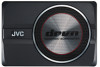
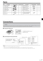
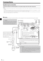
Parts No. Part Name ᶃ Remote control (5 m / 16 ft) ᶄ 10-pin connector cord (5 m / 16 ft) ᶅ Speaker cord (4.3 m/ 14 ft) ᶆ Fixture A ᶇ Fixture B Outside Shape Quantity No. Part Name 1 ᶈ Tapping screw (ø 5 × 16 mm (5/8")) 1 ᶉ Machine screw (M4 × 16 mm (5/8")) 1 ᶊ Tapping screw (ø 3 × 10 mm (3/8")) 2 Hook-and-loop fastener ᶋ (Double-side adhesive/ 1 for Remote control) Outside Shape Quantity 4 4 2 1 Connections Caution: Before wiring, be sure to remove the wire from the negative terminal of the battery. After completing all wiring, check the correct wirings again. After checking, connect the wire from the negative terminal of the battery. Terminals of Subwoofer POWER/SPEAKER INPUT terminal REMOTE terminal Connecting the remote control unit ᶃ Remote control Lights in blue. Connect with the lock part of remote control jack facing down. Lock part When the power turns ON, the illumination lights. Notes: • Be sure to connect the supplied remote control unit. • If the cord is not connected properly, the illumination on the remote control unit do not light up. • Do not insert the remote control connector upside down or forcibly. Otherwise, malfunction may result. 3 English
-
 1
1 -
 2
2 -
 3
3 -
 4
4 -
 5
5 -
 6
6 -
 7
7 -
 8
8 -
 9
9 -
10
-
11
-
12
-
13
-
14
-
15
-
16
-
17
-
18
-
19
-
20
-
21
-
22
-
23
-
24
-
25
-
26
-
27
-
28
-
29
-
30
-
31
-
32
-
33
-
34
-
35
-
36
-
37
-
38
-
39
-
40
-
41
-
42
-
43
-
44
-
45
-
46
-
47
-
48
-
49
-
50
-
51
-
52
-
53
-
54
-
55
-
56
-
57
-
58
-
59
-
60
-
61
-
62
-
63
-
64
-
65
-
66
-
67
-
68
-
69
-
70
-
71
-
72
-
73
-
74
-
75
-
76
-
77
-
78
-
79
-
80
 |
 |
