JVC KD-X210 Instruction Manual - Page 17
Part list for, installation, Wiring connection
 |
View all JVC KD-X210 manuals
Add to My Manuals
Save this manual to your list of manuals |
Page 17 highlights
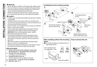
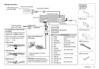
Wiring connection To Blue/white wire of the wiring harness (D) Remote wire (not supplied) JVC Amplifier Signal cord (not supplied) Rear/subwoofer output Fuse (10 A) Part list for installation (A) Faceplate (B) Trim plate To the steering wheel remote control adapter For some VW/Audi or Opel (Vauxhall) automobiles You may need to modify the wiring of the supplied power cord (D) as illustrated. If the unit does not turn on with modified wiring 1, use modified wiring 2 instead. Y: Yellow R: Red Original wiring Light blue/yellow STEERING WHEEL (For KD-X210) REMOTE If your car does NOT have an ISO terminal Modified wiring 1 ( or ) Modified wiring 2 * Custom wiring harness (separately purchased) IMPORTANT: A custom wiring harness (separately purchased) which is suitable for your car is recommended for connection. Aerial terminal ISO connector Pin Color and function A2 Brown : To mobile phone system A4 Yellow : Battery A5 Blue/White : Power control A6 Orange/white : Car light control switch A7 Red : Ignition (ACC) A8 Black : Earth (ground) connection B1 Purple B2 Purple/black : Rear speaker (right) B3 Gray B4 Gray/black : Front speaker (right) B5 White B6 White/black : Front speaker (left) B7 Green B8 Green/black : Rear speaker (left) (C) Mounting sleeve (D) Wiring harness (E) Extraction key ENGLISH | 15
-
 1
1 -
2
-
3
-
4
-
5
-
6
-
7
-
8
-
9
-
10
-
11
-
 12
12 -
 13
13 -
 14
14 -
 15
15 -
 16
16 -
 17
17 -
 18
18 -
 19
19 -
 20
20 -
 21
21 -
 22
22 -
23
-
24
-
25
-
26
-
27
-
28
-
29
-
30
-
31
-
32
 |
 |
