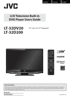
JVC LT-32D200 Instructions - Page 4
INTRODUCTION, Supplied Accessories, Attaching the Stand, Symbols Used in this Manual - remote control
 |
UPC - 046838037153
View all JVC LT-32D200 manuals
Add to My Manuals
Save this manual to your list of manuals |
Page 4 highlights
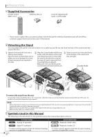
INTRODUCTION 5 Supplied Accessories remote control (RM-C-2152) batteries (AA x 2) AA AA Screw for attaching the stand x 4 (FPH34200) • If you need to replace these accessories, please refer to the part No. with the illustrations and call our toll free customer support line found on the cover of this manual. 5 Attaching the Stand You must attach the stand to the unit to have it as a table top unit. Be sure the front and rear of the stand match the proper direction. 1 2 Spread a thick and soft cloth over a Align the 2 stand hooks with the two table as shown below. hooks under the bottom of the main Place the main unit face down onto it. unit (shown by arrow ➀), then slide Make sure not to damage the screen. the stand in the direction as shown At least two people are required at by arrow ➁) until it stops and the 4 this step. mounting holes are aligned. Make sure not to put the AC power cord between the stand and the unit. 3 Drive screws in the 4 threaded holes at the bottom of the stand until they are tight. Ž screw holes f ront side Œ Œ To remove the stand from this unit Unscrew the screws indicated by above "➂". screw holes. After the screws are removed pull the stand up toward the rear of the unit. Be careful not to drop the stand when you remove it. Note: • When attaching the stand, ensure that all screws are tightly fastened. If the stand is not properly attached, it could cause the unit to fall, resulting in injuries as well as damage to the unit. • Make sure to use a table which can support the weight of this unit and is larger than this unit. • Make sure the table is in a stable location. 5 Symbols Used in this Manual The following is the description for the symbols used in this manual. Description refers to: TV FUNCTIONS TV : Analog TV operation DTV : Digital TV operation • If neither symbol appears under the function heading, operation is applicable to both. 4 EN DVD FUNCTIONS DVD : Playback of DVD-video CD : Playback of audio CD • If neither symbol appears under the function heading, operation is applicable to both.
-
 1
1 -
 2
2 -
 3
3 -
 4
4 -
 5
5 -
 6
6 -
 7
7 -
 8
8 -
 9
9 -
 10
10 -
11
-
12
-
13
-
14
-
15
-
16
-
17
-
18
-
19
-
20
-
21
-
22
-
23
-
24
-
25
-
26
-
27
-
28
-
29
-
30
-
31
-
32
-
33
-
34
-
35
-
36
-
37
-
38
-
39
-
40
-
41
-
42
-
43
-
44
-
45
-
46
-
47
-
48
-
49
-
50
-
51
-
52
-
53
-
54
-
55
-
56
 |
 |
