Kenmore 3103 Installation Instructions
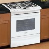
Kenmore 3103 - Elite 30 in. Slide-In Gas Range Manual
 |
View all Kenmore 3103 manuals
Add to My Manuals
Save this manual to your list of manuals |
Kenmore 3103 manual content summary:
- Kenmore 3103 | Installation Instructions - Page 1
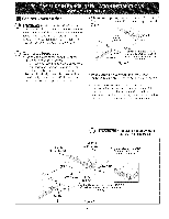
gas supplier's instructions. * If you cannot reach your gas supplier, calJ the fire department. -- Installation and service must be performed by a qualified instalJer, service agency or the gas supplier. Appliances ........... I WIDTH I FRONT OF RANGE (C0untert0Pand I Cabinet) I=: cUTouT - Kenmore 3103 | Installation Instructions - Page 2
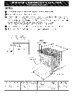
when the cabinet is unprotected. For cutouts below 22 7/8"(58.1 cm), appliance will slightly show out of the cabinet. q_! Allow at least 19 HEIGHT B: wiDTH • c] CoOKTOP D, DEPTH TO E. CUTOUT WIDTH . WDTH . FRONT OF RANGE (CauCnateb_intoept) and 35 5/8" (90.5crn)36 5/8" (93 cm) 30" (76,2 cm - Kenmore 3103 | Installation Instructions - Page 3
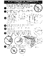
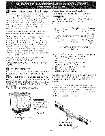
or could cause glass breakage voiding the warranty. Level the unit if needed. After the installation, MAKE SURE that the is supported by the leveling legs NOT by the cooktop. successfully install the range, the initial level height from floor to underside of cooktop glass should be at least 1/16 - Kenmore 3103 | Installation Instructions - Page 4
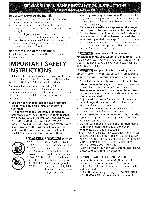
. As with any appliance using gas and generating heat, there are certain safety precautions you should follow. You will find them in the Use and Care Guide, read it carefully. • Be sure your range is installed and grounded properly by a qualified installer or service technician. This range must be - Kenmore 3103 | Installation Instructions - Page 5
© To eliminate the risk of cabinet burns and fire, do not have cabinet storage space above the range. If there is cabinet storage space above range, reduce risk by installing a range hood that projects horizontally a minimum of 5" (12.7 cm) beyond the bottom of the cabinet. © Countertop - Kenmore 3103 | Installation Instructions - Page 6
appliance shall be conducted according to the instructions in step 4. The gas supply line should be 1/2" or 3A" I.D. (Interior Diameter) |Seal the openings Seal any openings in the wall behind the range and in the floor under the range after gas supply line is installed. Connect the range to the gas - Kenmore 3103 | Installation Instructions - Page 7
cord from wall receptacle before servicing cooktop. Moving the Appliance for Servicing and Cleaning Turn off the range line fuse or circuit breakers at the main power source, and turn off the manual gas shut-off valve. Make sure the range is cold. Remove the service drawer (warmer drawer on some - Kenmore 3103 | Installation Instructions - Page 8
is an added convenience. Refer to the Use and Care Guide for oven door removal instructions, Standard Installation The range cooktop overlaps the countertop at the sides and the range rests on the floor. The cooktop is 31 1/2" (81 cm)wide. Install base cabinets 30" (76.2 cm) apart. Make sure they - Kenmore 3103 | Installation Instructions - Page 9
be ordered through a Sears Service Center. 2. Follow instructions supplied with your new side trims to replace the actual side trims with the new ones. 3. Check if the countertop is prepared for 29" cutout wide opening at page 7. 4. Install range as in the "Installation Without Side Panels" section - Kenmore 3103 | Installation Instructions - Page 10
Guide packaged with the range for operating instructions and for care and cleaning of your range. Remove all packaging from the oven before testing. 11.1 Install Burner Bases and Burner Caps This range this range. Electrode Figure 1 1 11.2 Turn on Electrical Power and Open Main Shutoff Gas Valve - Kenmore 3103 | Installation Instructions - Page 11
a temperature sufficient to ignite gas, the electrically controlled oven valve ordering parts for or making inquiries about your range, range was adjusted for when it left the factory. Before You Call for Service Read the Before You Call Checklist and operating instructions in your Use and Care Guide - Kenmore 3103 | Installation Instructions - Page 12
-Tip Brackets Installation instructions Models Equipped with Leveling Device To reduce the risk of tipping of the range, the range must be secured to the floor by properly installed anti-tip bracket and screws packed with the range. These parts are located in the oven. Failure to install the anti - Kenmore 3103 | Installation Instructions - Page 13
weight is placed on an open door or if a child climbs upon it. Serious injury might result from spilled hot liquids or from the range itself. Follow the instructions below to install the anti-tip brackets. If range is ever moved to a different location, the anti-tip brackets must also be moved and - Kenmore 3103 | Installation Instructions - Page 14
NOTES - Kenmore 3103 | Installation Instructions - Page 15
gas licenciado de Massachusett. Este aparato se debe instalar con un largo conector flexible de gas de tres (3) pies/36 pulgadas. Una wilvula manual de gas del armario derecho y de 2" a4" (5.1 cma 10.2 cm) del suelo. No instale la unidad en el gabinete si no ha leido esta p_igina. A ALTURA I B: - Kenmore 3103 | Installation Instructions - Page 16
para la profundidad cuando este abierta. 22 7/8" (58.1 cm) min. 23 1/4" (59.05 cm) max. ÷ (yea la nota 4) ÷ r de la puerta PARTE DELANTERA DEL ARMARIO 1 1/8" °(2.86 cm) Ref. 21¾" Puerta abierta (vea la nota 5) \ // / i Panel lateral A. ALTURA I B. ANCHO I, CI ANCHO DE LAD. PROFUNDIDAD - Kenmore 3103 | Installation Instructions - Page 17
_irea sombreada en la ilustracion n0mero 1) Antes de instalar la unidad, mida la altura de los dos (2)lados de los gabinetes (H1-4), frente y parte trasera (vea ilustracion 1) del piso a Io alto de la cubierta. Nivele la estufa usando Lime el las 4 patas niveladoras de borde levantado manera - Kenmore 3103 | Installation Instructions - Page 18
las estufas pueden volcarse. • Esto podria resultar en lesiones personales. Instale el dispositivo antivuelcos que se ha empacado junto con esta estufa. Para las instrucciones de prelimpiado en el Manual del Usuario. • A diferencia de la gama est_ndar cocinas de gas, ESTA PLANCHA DE COCINA NO ES - Kenmore 3103 | Installation Instructions - Page 19
en el suelo debajo de la estufa despu_s que la linea del suministro de gas sea instalada. 29"(73,7 cm) (Figura 2 3/16" 5 cm) 3): 2 3/16" (5.56 cm) Quite el 2 3/16" material de frente parte posteriora. 1%" de a la 30" (3,2 cm) I (76.2 cm) 311/2"z (81 cm) Mostrador moldeado o !jo recortado - Kenmore 3103 | Installation Instructions - Page 20
en la superficie de la estufa o en la linea de suministro. Desconecte la estufa y su valvula de cierre manual del sistema de tuberia del suministro de gas durante cualquier prueba de presiOn de ese sistema a presiones mayores de 1/2 psig (3,5 kPa o 14" columna de agua). Aisle la estufa del sistema - Kenmore 3103 | Installation Instructions - Page 21
La mudanza de[ aparato para reparaciones o limpieza Apague la corriente electrica a la estufa a la fuente de poder principal, y apague la wilvula de cierre manual de gas. Aseg0rese de que la estufa este fresca. Quite el cajon de servicio (el cajon calentador en algunos modelos) y abre la puerta del - Kenmore 3103 | Installation Instructions - Page 22
esten verticales y alineados antes de instalar la plancha de cocinar. Lije el horde del mostrador para obtener las 31 1/2 (81 cm)" en la parte superior del mostrador. Instale las puertas del armario a 31 " (78,7 cm) de espacio entre elias para que no interfieran con la abertura de la puerta de la - Kenmore 3103 | Installation Instructions - Page 23
de haberla instalado en la abertura del mostrador. 1. Abra la gaveta. 2. Baje el aparato, las 4 patas de nivelaci0n alternadamente, hasta que la parte baja de la superficie de cocci6n repose sobre el mostrador (Figura 8). 3. Verifique si la cocina est,1 nivelada colocando una parrilla en el centro - Kenmore 3103 | Installation Instructions - Page 24
parte superior de la cocina debe estar ubicada sobre el accesorio decorativo). /;/ , Figura 11 electroao 11.2 Endende ia corriente electrka y abre ia vaivula principal de derre. trasero Figura 10 Comprobacidn dei funaonamiento Consulte el Manual de suministro de gas. Controle visualmente que - Kenmore 3103 | Installation Instructions - Page 25
Cuando el encendedor a alcanzado una temperatura suficiente para encender el gas, la wilvula del homo controlada el@ctricamentese abrir_i y el fuego el fondo del homo, retire los tornillos de ajuste del homo en la parte posteior del fondo del homo. jale hacia arriba, desenganche el frente del fondo - Kenmore 3103 | Installation Instructions - Page 26
garantfa y la informacion sobre el servicio en su Manual del Usuario para obtener el n0mero de telefono la cocina. Si no hay pared posterior, dibujar otra Ifnea en el piso que corresponda a la parte posterior de la cocina. 2. Desplegar el molde de papel y colocarlo alisado sobre el piso con el - Kenmore 3103 | Installation Instructions - Page 27
est,1 instalando en concreto) Los soportes se fijan al suelo en la parte trasera de la estufa para sujetar ambos niveladores de las patas traseras. piso con los hordes laterales y el trasero colocados exactamente donde la parte trasera y los lados de la estufa ser_n colocados cuando sea instalada - Kenmore 3103 | Installation Instructions - Page 28
[] W-6 W-14 C2 OVEN ClRCUIT//CIRCUITO DE HORNO//CIRCUIT FOUR W-19 ELECTRONIC OVEN CONTROL/ CONTROL DE HORNO ELECTRONZCO/ CONTROLE ELECTRONIQUE FOUR R-6 J OVEN LAMP/LAMPARA DEL _ HORNO/LAMPE DE FOUR _ _" _ B R-14 LAMP OVEN HALOGEN/LAMPABA HALOGENE/LUMIERE LAMP/LAMPARA //'\,DBL
-
 1
1 -
 2
2 -
 3
3 -
 4
4 -
 5
5 -
 6
6 -
 7
7 -
8
-
9
-
10
-
11
-
12
-
13
-
14
-
15
-
16
-
17
-
18
-
19
-
20
-
21
-
22
-
23
-
24
-
25
-
26
-
27
-
28
 |
 |
iNSTALLATiON
AND
SERVICE
MUST BE PERFORMED BY A QUALiFiED
iNSTALLER.
IMPORTANT: SAVE FOR LOCAL ELECTRICAL INSPECTOR'S USE.
READ AND SAVE THESE iNSTRUCTiONS FOR FUTURE REFERENCE.
if the information
in this manual
is not followed
exactly,
a fire
or
expJosion
may resuJt causing
property
damage,
personal
injury
or death.
FOR YOUR SAFETY:
--
Do not store
or use gasoline
or other
flammable
vapors
and liquids
in the
vicinity
of this or any other
appliance.
--
WHAT
TO DO iF YOU SMELL GAS:
*
Do not try to light
any appliance.
.
Do not touch
any eJectrical switch;
do not use any phone
in your
buiJding.
*
Immediately
calJ your
gas supplier
from
a neighbor's
phone.
Follow
the
gas supplier's
instructions.
*
If you cannot
reach your
gas supplier,
calJ the fire
department.
--
Installation
and service
must
be performed
by a qualified
instalJer,
service
agency
or the gas supplier.
Appliances
InstalJed
in the
state
of
Massachusetts:
This Appliance
can only be
installed in the state of
Massachusetts
by a
Massachusetts
licensed plumber
or gasfitter.
This appliance
must be installed
with
a three (3) foot
/
36 in. long
flexible
gas connector.
A"T"
handle type manual gas
valve must be installed in the gas
supply line to this appliance.
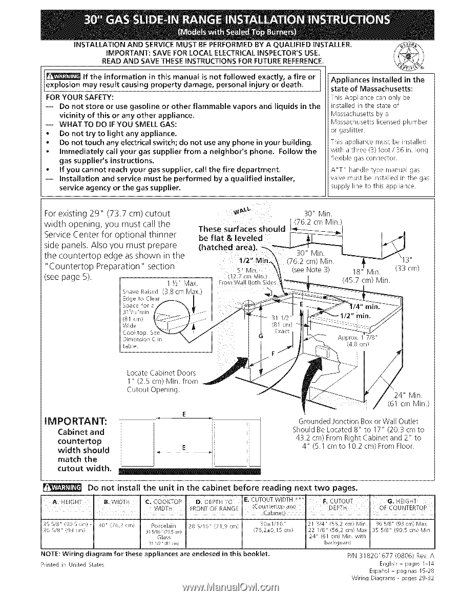
For existing
29"
(73.7 cm) cutout
width
opening,
you must call the
Service Center for optional
thinner
side panels. Also you must prepare
the countertop
edge as shown
in the
"Countertop
Preparation"
section
(see page 5).
Shave
Raised
Edge
to
Clear
Space
for
a
31s/16"min
(81
cm)
Wide
Cooktop.
Dimension
C in
table.
11/2 Max.
(3.8 cm Max.
These
surfaces
should
be flat
& leveled
(hatched
area).
1/2" Min_,
5"
M n.
(12.7 cm Min.J
From
Wall
Both
Sioes
30" Min.
(76.2 cm Min
30"
Min.
\13"
(see Note 3)
18" Min.
(33 cm)
(45.7 cm) Min.
IM PO RTA NT:
Cabinet
and
countertop
width
should
match
the
cutout
width.
Locate
Cabinet
Doors
1" (2.5
cm) Min.
from
Cutout
Opening.
E
ii
l
24" Min.
(61 cm Min.)
Grounded Jonction Box or Wall Outlet
Should Be Located 8" to 17" (20.3 cm to
43.2 cm) From Right Cabinet and 2" to
4" (5.1 cm to 10.2 cm) From Floor.
Do not
install
the
unit
in the
cabinet
before
reading
next
two
pages.
A
HE
GHT
Bi
WIDTH
Cl
COoKTOP
ID: DEPTH
IF:
CUTOUT
WIDTH _**
I=:
cUTouT
GI
HEIGHT
I
...........
I
WIDTH
I FRONT OF RANGE
(C0untert0Pand
I
DEPTH
OFCOUNTERTOP
Cabinet)
35 5/8"
(90.5cm)-
30"
(76,2
cm)
Porcelain
28 5/16"
(71,9
cm)
30_+1/16"
21 3/4"
(55,2
cm)
Min.
36 5/8"
(93cm)
Max.
36
5/8"
(93
cm)
315/16"(79.5cm)
(76,2_+0,15
cm)
22 1/8"
(56,2
cm)
Max
35
5/8"
(90.5
cm)
Min.
Glass
24"
(61
cm)
Min.
with
31 1/2" (81 crn)
backguard
NOTE:
Wiring
diagram
for
these
appliances
are
enclosed
in this
booklet.
Printed
in United
States
P/N 318201677
(0806)
Rev. A
English - pages 1-14
Espahol - p_iginas 15-28
Wiring
Diagrams
- pages 29-32