Kenmore 3103 Installation Instructions - Page 1
Kenmore 3103 - Elite 30 in. Slide-In Gas Range Manual
 |
View all Kenmore 3103 manuals
Add to My Manuals
Save this manual to your list of manuals |
Page 1 highlights
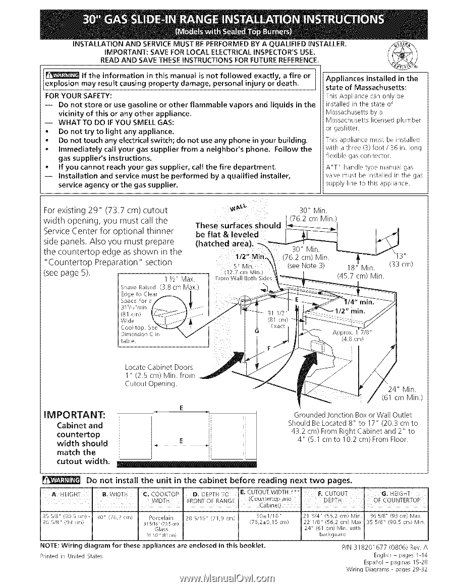
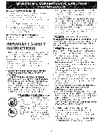
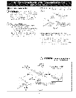
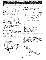
iNSTALLATiON AND SERVICE MUST BE PERFORMED BY A QUALiFiED iNSTALLER. IMPORTANT: SAVE FOR LOCAL ELECTRICAL INSPECTOR'S USE. READ AND SAVE THESE iNSTRUCTiONS FOR FUTURE REFERENCE. if the information in this manual is not followed exactly, a fire or expJosion may resuJt causing property damage, personal injury or death. FOR YOUR SAFETY: -- Do not store or use gasoline or other flammable vapors and liquids in the vicinity of this or any other appliance. -- WHAT TO DO iF YOU SMELL GAS: * Do not try to light any appliance. . Do not touch any eJectrical switch; do not use any phone in your buiJding. * Immediately calJ your gas supplier from a neighbor's phone. Follow the gas supplier's instructions. * If you cannot reach your gas supplier, calJ the fire department. -- Installation and service must be performed by a qualified instalJer, service agency or the gas supplier. Appliances InstalJed in the state of Massachusetts: This Appliance can only be installed in the state of Massachusetts by a Massachusetts licensed plumber or gasfitter. This appliance must be installed with a three (3) foot / 36 in. long flexible gas connector. A"T" handle type manual gas valve must be installed in the gas supply line to this appliance. For existing 29" (73.7 cm) cutout width opening, you must call the Service Center for optional thinner These surfaces should be flat & leveled side panels. Also you must prepare the countertop edge as shown in the "Countertop Preparation" section (hatched area). 1/2" Min_, 5" M n. (see page 5). 1 1/2 Max. (12.7 cm Min.J From Wall Both Sioes Shave Raised Edge to Clear Space for a 31s/16"min (3.8 cm Max. (81 cm) Wide Cooktop. Dimension table. C in 30" Min. (76.2 cm Min 30" Min. (see Note 3) \13" 18" Min. (33 cm) (45.7 cm) Min. Locate Cabinet Doors 1" (2.5 cm) Min. from Cutout Opening. IM PO RTA NT: Cabinet and countertop width should match the cutout width. E ii l 24" Min. (61 cm Min.) Grounded Jonction Box or Wall Outlet Should Be Located 8" to 17" (20.3 cm to 43.2 cm) From Right Cabinet and 2" to 4" (5.1 cm to 10.2 cm) From Floor. Do not install the unit in the cabinet before reading next two pages. A HE GHT Bi WIDTH Cl COoKTOP ID: DEPTH IF:CUTOUT WIDTH _** I ........... I WIDTH I FRONT OF RANGE (C0untert0Pand I Cabinet) I=: cUTouT DEPTH GI HEIGHT OFCOUNTERTOP 35 5/8" (90.5cm)36 5/8" (93 cm) 30" (76,2 cm) Porcelain 315/16"(79.5cm) Glass 31 1/2" (81 crn) 28 5/16" (71,9 cm) 30_+1/16" (76,2_+0,15 cm) NOTE: Wiring diagram for these appliances Printed in United States are enclosed in this booklet. 21 3/4" (55,2 cm) Min. 22 1/8" (56,2 cm) Max 24" (61 cm) Min. with backguard 36 5/8" (93cm) Max. 35 5/8" (90.5 cm) Min. P/N 318201677 (0806) Rev. A English - pages 1-14 Espahol - p_iginas 15-28 Wiring Diagrams - pages 29-32
-
 1
1 -
 2
2 -
 3
3 -
 4
4 -
 5
5 -
 6
6 -
 7
7 -
8
-
9
-
10
-
11
-
12
-
13
-
14
-
15
-
16
-
17
-
18
-
19
-
20
-
21
-
22
-
23
-
24
-
25
-
26
-
27
-
28
 |
 |