Kenmore 4102 Installation Instructions
Kenmore 4102 - Elite 30 in. Slide-In Electric Range Manual
 |
View all Kenmore 4102 manuals
Add to My Manuals
Save this manual to your list of manuals |
Kenmore 4102 manual content summary:
- Kenmore 4102 | Installation Instructions - Page 1
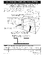
iNSTALLER. iMPORTANT: SAVE FOR LOCAL ELECTRICAL iNSPECTOR'S USE. READ AND SAVE THESE iNSTRUCTiONS FOR FUTURE REFERENCE. For existing 29" (73.7 cm) cutout wide opening, you must 30" Min. call the Service D. TOTAL DEPTH WIDTH TO FRONT OF • RANGE IE; CUTOUT WIDTH*** _Countertop and cabinet) 31 - Kenmore 4102 | Installation Instructions - Page 2
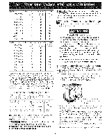
(seenote 5) \\ A: HEIGHT (Under Cooktop) 35 5/8" (90.5 cm} 36 5/8" (93 cm) B.WIDTH C. COOKTOP , DI TOTAL DEPTH E. CUTOUT WIDTH*** I W!DTH. TO FRONT QF RANGE " (Countertop. and cabinet) 30" (76,2 cm) 315116" (79.5 cm) 28 5/16" (71,9 cm} 30±1116" (76,2±0,15 cm} , OF COUNTERTOR " • 213 - Kenmore 4102 | Installation Instructions - Page 3
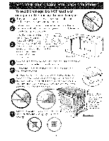
Cooktop. cabinet measurement by at least 1/1 6" (see illustration 2). Illustration 1 Slide the unit into the cabinet. Make sure the center of the unit is aligned the installation, MAKE SURE that the uni is supported by the leveling legs NOT by the cooktop. ..:to successfullyinstall the range, the - Kenmore 4102 | Installation Instructions - Page 4
Note to the Consumer Keep these instructions with your owner's guide for future reference. IMPORTANT SAFETY INSTRUCTIONS • Be sure your range is installed and grounded properly by a qualified technician. installer or service • This range must be electrically grounded in accordance with local - Kenmore 4102 | Installation Instructions - Page 5
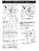
Slide-in Range is shipped from factory with I-I/8" dia. hole as shown on figure 3. If a larger hole is required, punch out the knockout. Risk of fire or electrical shock exists if an incorrect size range cord kit is used, the InstalJation Instructions are not foJJowed, or the strain reJief bracket - Kenmore 4102 | Installation Instructions - Page 6
installed at this location To 240 V receptacle I-I/8" Dia. Direct Connection Hole. Punch out knockout Figure 3 for I-3/8" Dia. Cord Kit Hole Four Conductor Wire Connection to Range the terminal cover and replace the 3 screws. Direct Electrical Connection to the Circuit Breaker, Fuse Box or - Kenmore 4102 | Installation Instructions - Page 7
cm) dimension. Electrical System (Example: Junction Box) Cabinet Construction (__ To eliminate the risk of burns or fire by reaching over heated surface units, do not have cabinet storage space above the range. If there is cabinet storage space above range, reduce risk by installing a range - Kenmore 4102 | Installation Instructions - Page 8
Note: Door removal is not a requirement for installation of the range, but is an add_A rr_n\/pnipn¢p Refer to the Use and Guide for oven door removal instructions. Care Standard Installation The range cooktop overlaps the countertop at the I sides and the range rests on the floor. The cooktop is - Kenmore 4102 | Installation Instructions - Page 9
Sears Service Center. 2. Follow instructions supplied with your new side trims to replace the actual side trims with the new ones. 3. Check if the countertop is prepared for 29" cutout wide opening at page 7. 4. Install range as in the "Installation the countertop, slide range into cutout opening - Kenmore 4102 | Installation Instructions - Page 10
model and serial numbers and a lot number or letter from the serial plate on your range. Before You Call for Service Read the Before You Call for Service Checklist and operating instructions in your Use & Care Guide. It may save you time and expense. The list includes common occurrences that are not - Kenmore 4102 | Installation Instructions - Page 11
the range itself. Follow the instructions below to install the anti-tip brackets. If range electrical wiring or plumbing. The screws provided will work in either wood or concrete. 1. Draw a center line (CL) on the floor where the range should be installed. Also draw a line on the floor at the range - Kenmore 4102 | Installation Instructions - Page 12
hot liquids or from the range itself. Follow the instructions below to install the anti-tip brackets. If range is ever moved to a range and the rear leg levelers to allow room for the anti-tip brackets. 5. Slide range into place making sure rear legs are trapped by ends of brackets. Range - Kenmore 4102 | Installation Instructions - Page 13
de 29" (73,7 cm), tiene que Ilamar al Centro de Servicios Sears y solicitar paneles laterales opcionales. (76.230"cm)M, rnMrn. !_--___ de la cubierta y el armario debe de set igual al ancho del torte. E No instale la unidad en el gabinete si no ha leido esta p_igina. A ALTURA ' (Debajo de - Kenmore 4102 | Installation Instructions - Page 14
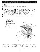
NOTAS: @ No pellizque el cordon electrico entre la estufa y la pared. @ No selle la estufa a los armados de lado. 0 Un espado minimo de 24" (61 cm) entre la superficie de la estufa y el fondo del armario esto cuando el rondo de] armario de madera o metal esta protegido pot no menos de 1/4" (0.64 cm) - Kenmore 4102 | Installation Instructions - Page 15
del gabinete mas alto de su mobiliario de Lime el horde levantado 1 Y2" Max. (3.8 cm Max.) para dejar espacio para una unidad con un dimension 31 Y2" (81 cm). cocina pot Io menos pot 1/1 6" (vea ilustracion 2). Ilustracion 1 @Deslice la unidad hacia el gabinete. Aseg0rese que la unidad este - Kenmore 4102 | Installation Instructions - Page 16
o de no existir, con la National Electrical Code ANSI/NFPA No.70- _ltima edici6m no se aplica, la Standard for Manufactured Home Installation 1982 (Manufactured Home sites, communities and setups) Siga las instrucciones para la prelimpieza en el Manual del usuario. Estuche de cable del suministro el - Kenmore 4102 | Installation Instructions - Page 17
Grado de vatios del electrodomestico 120V 1208V 0-3120 3121-3900 3901-4160 4161-5200 5201-5570 5571-7430 7431-7800 7801-12500 12501-14500 Tamario minimo del conductor AWG Conductores L1 yL2 16 16 14 14 12 12 12 10 8 Conductor Neutral 16 16 16 16 16 14 12 12 12 Conductor de Tierra 14 12 12 10 10 - Kenmore 4102 | Installation Instructions - Page 18
terminal plata Alambre . Bloque terminal plata Alambre Rojo Alambre Negro Una arazadera de releva provista debe de estar instalada a esta ubicacion 240 V receptaculo 1-1/8" Dia. Agujero de la conexi6n directa. Retira la arandela pre-cortada para 1-3/8" Dia. Agujero Figura 3 Conexi6n deJ - Kenmore 4102 | Installation Instructions - Page 19
Alambre Blanco (Neutro) Alambres_ rojo Cable de la fuente de alimentaci6n Alambres negros _ja de empalmes Alambres desnudos o verdes Cable de la estufa Figura 5 - Sistema el_ctrico empalmes) de 3 alambres Blanco (Neutro) Conductor de uni6n listado-UL (listado-CSA) (ejemplo: caja de (a - Kenmore 4102 | Installation Instructions - Page 20
y alineados antes de instalar la plancha de cocinar. Lije el horde del mostrador para obtener las 31 I/2 (81 cm)" en la parte superior del mostrador. Instale las puertas del armario a 31 " (78,7 cm) de espacio entre elias para que no inteffieran con la abertura de la puerta de la cocina. Corte - Kenmore 4102 | Installation Instructions - Page 21
. La moldura trasera puede ser pedida con su representante. Instalaci6n con Paneles Laterales Llenos Los Paneles Laterales puede set pedidos con su representante. Instale las puertas de los armarios a 31 " (78.7 cm) de espacio entre elias para que no interfieran con la abertura de la puerta de - Kenmore 4102 | Installation Instructions - Page 22
con el n0mero de serie de su cocina. Antes de Ilamar al servicio Lea la secciOn Lista de Antes de Ilamar en su Manual del Usuario. Estolepodraahorrartiempoygastos. Esta lista incluye ocurrencias comunes que no son el resultado de defectos de materiales o fabricaciOn de este artefacto. Lea la - Kenmore 4102 | Installation Instructions - Page 23
[t Jlnstrucciones de instalaci6n de la fijacion anti-inclinaciOn - Modelos con una cubierta ceramico vidriado Para los modelos equipado con un sistema de dipositivo de nivelaci6n. Para reducir el riesgo de inclinaciOn de la cocina, esta debe ser asegurada hacia el piso con las fijaciones de anti- - Kenmore 4102 | Installation Instructions - Page 24
Para los modeJos equJpado con las patas niveladoras. 11_ Para reducir el riesgo de inclinaci6n de la cocina, 6sta debe ser asegurada hacia el piso con las fijaciones de anti-inclinaci6n y los tornillos que vienen con la cocina. Estos componentes se encuentran en el horno. Si no instala las
-
 1
1 -
 2
2 -
 3
3 -
 4
4 -
 5
5 -
 6
6 -
 7
7 -
8
-
9
-
10
-
11
-
12
-
13
-
14
-
15
-
16
-
17
-
18
-
19
-
20
-
21
-
22
-
23
-
24
 |
 |
iNSTALLATiON
AND
SERVICE
MUST
BE PERFORMED
BY A QUALiFiED
iNSTALLER.
iMPORTANT:
SAVE
FOR LOCAL ELECTRICAL
iNSPECTOR'S
USE.
READ AND
SAVE
THESE iNSTRUCTiONS
FOR FUTURE
REFERENCE.
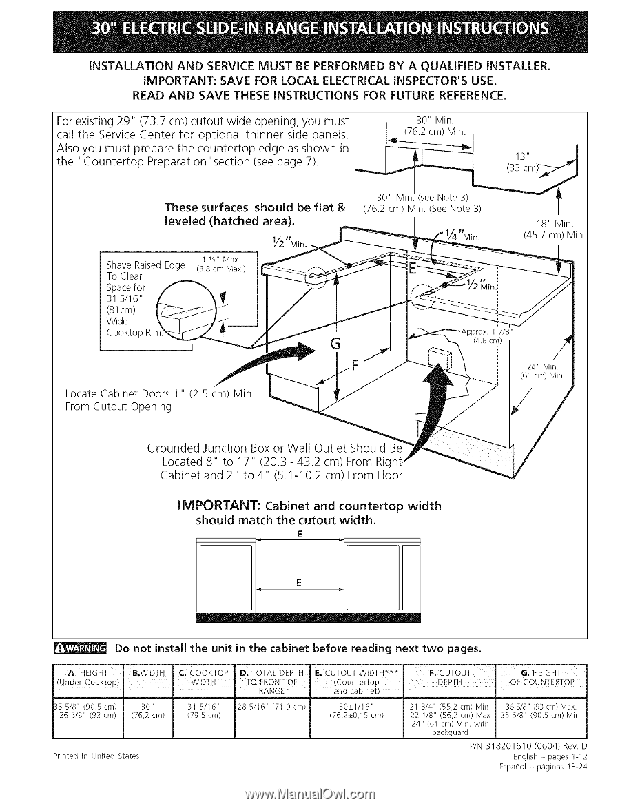
For existing 29"
(73.7 cm) cutout
wide opening,
you must
call the Service Center
for
optional
thinner
side panels.
Also you must prepare
the countertop
edge as shown
in
the "Countertop
Preparation"
section (see page 7).
These
surfaces
shouJd
be flat
&
leveled
(hatched
area),
Shave Raised Edge
To Clear
Spacefor
31 5/16"
(81cm)
Wide
Cooktop Rir
1
Y/'
Max.
(3.8 cm Max.)
30" Min.
(76.2 cm) Min.
,
J
30" Min.l(see Note 3) __
(76.2 cm) Min. (See Note 3)
|
18" Min.
Min.
(45.7 cm) Min.
Locate
Cabinet
Doors
1"
(2.5
cm) Min.
From Cutout
Opening
Grounded
Junction
Box or Wall
Outlet
Should
Located 8" to 17"
(20.3 - 43.2 cm) From Rig
Cabinet
and 2" to 4"
(5.1-10.2
cm) From Floor
IMPORTANT:
Cabinet
and
countertop
width
shouJd
match
the cutout
width,
E
E
Do
not
instalJ
the
unit
in the
cabinet
before
reading
next
two
pages.
A.
HEIGHT
(Under
Cooktop)
35
518"
(90.5
cm)
-
36 518"
(93
cm}
B.WIDTH
30"
(76,2 cm)
Printed
in United
States
C.¸
COOKTOP
D. TOTAL
DEPTH
WIDTH
TO FRONT OF
•
RANGE
31 5/I6"
28 5/I6"
(71,9 cm)
(79.5 cm)
IE; CUTOUT WIDTH***
F. CUTOUT
'
G:
HEIGHT
_Countertop
DEPTH
OF COUNTERTOP
and cabinet)
"
30±1/I
6"
21 3/4"
(55,2 cm} Min.
36 5/8" (93 cm) Max.
(76,2±0,15cm)
22 118" (56,2 cm) Max
35 518" (90.Scm}Min.
24" (61 cm) Min. with
backguard
P/N 318201610
(0604)
Rev. D
English - pages 1-12
EspaF_ol- paginas
13-24