Kenmore 7800 Installation Instructions
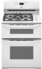
Kenmore 7800 - Elite 30 in. Double Oven Gas Range Manual
 |
UPC - 883049211312
View all Kenmore 7800 manuals
Add to My Manuals
Save this manual to your list of manuals |
Kenmore 7800 manual content summary:
- Kenmore 7800 | Installation Instructions - Page 1
SAFETY 2 INSTALLATION REQUIREMENTS 3 Tools and Parts 3 Location Requirements 3 Electrical Requirements 5 Gas Supply Requirements 5 INSTALLATION INSTRUCTIONS 6 Unpack Range 6 Adjust Leveling Legs 7 Install Anti-Tip Bracket 7 Make Gas Connection 8 Verify Anti-Tip Bracket Location - Kenmore 7800 | Installation Instructions - Page 2
RANGE SAFETY Your safety and the safety of others are very important, We have provided many important safety messages in this manual and on instructions. • If you cannot reach your gas supplier, call the fire department. - Installation and service must be performed by a qualified installer, service - Kenmore 7800 | Installation Instructions - Page 3
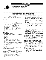
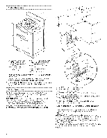
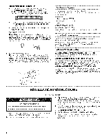
• Recessed installations must provide complete enclosure of the sides and rear of the range. Gather the required tools and parts before starting installation. Read and follow the instructions provided with any tools listed here. Tools needed • Tape measure • Phillips screwdriver • Flat - Kenmore 7800 | Installation Instructions - Page 4
and 36" (91.4 cm) countertop height. IMPORTANT: If installing a range hood or microwave hood combination above the range, follow the range hood or microwave hood combination installation instructions for dimensional clearances above the cooktop surface. Range may be installed with zero clearance to - Kenmore 7800 | Installation Instructions - Page 5
cord. Failure to follow these instructions can result in death, fire, or electrical shock. IMPORTANT: The range must be electrically grounded in accordance supplier. LP gas conversion: Conversion must be done by a qualified service technician. No attempt shall be made to convert the appliance from - Kenmore 7800 | Installation Instructions - Page 6
system by closing its individual manual shutoff valve during any pressure testing of the gas supply piping system at test pressures equal to or less than 1/2psi (3.5 kPa). A. Gas supply line B. Shutoff valve "open" position C. To range INSTALLATION INSTRUCTIONS Excessive Weight Hazard Use two - Kenmore 7800 | Installation Instructions - Page 7
hardboard. .........I... , _. _--. Tip Over Hazard A child or adult can tip the range and be killed. Connect anti-tip bracket to rear range foot. Reconnect the anti-tip bracket, if the range is moved. Failure to follow these instructions can result in death or serious burns to children and adults - Kenmore 7800 | Installation Instructions - Page 8
personnel, authorized gas company personnel, and authorized service personnel. Failure to do so can result in Adapter C. Flexible connector D. Manual shutoff valve Complete connection 1. Open the manual shutoff valve in the follow these instructions can result in death, fire, or electrical shock. 4. - Kenmore 7800 | Installation Instructions - Page 9
the control knobs to "Off" and contact your dealer or authorized service company for assistance. Adjust Flame Height Adjust the height of top burner on rack and check levelness of range, first side to side; then front to back. 3. If range is not level, pull range forward until rear leveling leg is - Kenmore 7800 | Installation Instructions - Page 10
authorized service Guide for specific instruction on range operation. If range does not operate, check the following: • Household fuse is intact and tight, or circuit breaker has not tripped. • Range is plugged into a grounded 3 prong outlet. • Electrical supply is connected. • See "Troubleshooting - Kenmore 7800 | Installation Instructions - Page 11
authorized service range and be killed. Connect anti-tip bracket to rear range foot. Reconnect the anti-tip bracket, if the range is moved. Failure to follow these instructions can result in death or serious burns to children and adults. 1. Turn manual Guide for oven door removal instructions, 11 - Kenmore 7800 | Installation Instructions - Page 12
3. Using a Phillips screwdriver, remove and set aside the 2 oven bake burner cover screws located at the front of the oven. A 8. Unscrew and remove the cover over the orifice. A B A. Bake burner cover B. Bake burner cover screws 4. Lift up and remove oven bake burner cover. 5. Unscrew 2 wing nuts - Kenmore 7800 | Installation Instructions - Page 13
11. Position the oven bake burner over the orifice hood and reinstall using 2 screws, 3. Turn the Number 1.42 Natural gas broil burner orifice hood counterclockwise to remove. A A. Bake burner orifice hood B. Oven bake burner C. Oven bake burner screws To Convert Upper Oven Bake Burner 12. Repeat - Kenmore 7800 | Installation Instructions - Page 14
A child or adult can tip the range and be killed. Connect anti-tip bracket to rear range foot. Reconnect the anti-tip bracket, if the range is moved. Failure to follow these instructions can result in death or serious burns to children and adults. 1. Turn manual shutoff valve to the closed position - Kenmore 7800 | Installation Instructions - Page 15
Burner: 1. Remove oven racks from inside the oven cavity. 2. Remove oven door. See "Oven Door" section in the Use and Care Guide for oven door removal instructions. 3. Using a Phillips screwdriver, remove and set aside the 2 oven bake burner cover screws located at the front of the oven. A. Igniter - Kenmore 7800 | Installation Instructions - Page 16
9. Turn the Number .047 LP gas orifice hood counterclockwise to remove. // // // / / // / // // i/ A. Number .047 LP gas orifice hood 10. Install the Number .0723 Natural gas orifice hood, turning it clockwise 4 or 5 turns. Do not overtighten. To Convert Oven Broil Burner 1. Remove broil - Kenmore 7800 | Installation Instructions - Page 17
Natural orifice spuds for each burner location, Natural Gas Orifice Spud Chart Burner Rating Color Number 5,000 BTU Clear 11 ON 9,200 BTU Clear 150N 12,000 BTU Clear 170N 16,000 BTU Clear 195N 5. Replace the LP gas orifice spud with correct Natural gas orifice spud. See the "Natural - Kenmore 7800 | Installation Instructions - Page 18
DE LA ESTUFA Su seguridad y la seguridad de los demas es muy importante. Hemos incluido muchos mensajes importantes de seguridad en este manual y en su electrodomestico. Lea y obedezca siempre todos los mensajes de seguridad. Este simbolo le llama la atenci6n sobre peligros potenciales que pueden - Kenmore 7800 | Installation Instructions - Page 19
corrosiva • Destornillador de cuchilla plana de 1/8" Para las conversiones de gas natural/LP • Nivel • Llave de combinaci6n de1/2" • Taladro manual o electrico • Llave de tuerca o pinzas • Llave detuercas de %2" (7,0 mm) • Uave para tubos • Cinta adhesiva protectora • Llave de combinaci6n - Kenmore 7800 | Installation Instructions - Page 20
• Deben usarse las dimensiones de la abertura del armario que se muestran. Las dimensiones proporcionadas son los espacios minimos. • Debe instalarse el soporte anti-vuelco del piso. Para instalar el soporte anti-vuelco enviado con la estufa, vea la secci6n "lnstalaci6n del soporte anti-vuelco'. • - Kenmore 7800 | Installation Instructions - Page 21
La estufa se puede instalar sin dejar ningun espacio para la construcci6n para la combusti6n en la parte posterior de la estufa y a los lados por debajo de la superficie de cocci6n. NOTA: 24" (61,0 cm) minimo cuando la base del armario de madera o de metal este protegida por cart6n retardante alas - Kenmore 7800 | Installation Instructions - Page 22
para que la estufa este nivelada y alineada. Debe tenet una valvula de cierre: La Ifnea de suministro debera equiparse con una valvula de cierre manual. Esta valvula debera estar ubicada en la misma habitaci6n pero fuera de la estufa. Debera estar en una ubicaci6n que permita un facil acceso para - Kenmore 7800 | Installation Instructions - Page 23
(14" WCP) o menor La estufa debera aislarse del sistema de tuberfa del suministro de gas cerrando la vMvula de cierre individual manual durante toda prueba de presi6n efectuada en dicho sistema a presiones de prueba iguales o menores de 1/2Ibs/pulg 2 (3,5 kPa). INSTRUCCIONES DE INSTALACION - Kenmore 7800 | Installation Instructions - Page 24
NOTA: Si se ajusta la altura cuando la estufa esta de pie, inclinela hacia atras para ajustar las paras delanteras y luego inclinela hacia delante para ajustar las patas traseras. Montaje a trav_s de la pared 3. Cuando la estufa este a la altura correcta, cerci6rese de que hay un espacio adecuado - Kenmore 7800 | Installation Instructions - Page 25
de gas B. Use compuesto para juntas de tube@ C. Adaptador (deber4 tenet una rosca macho para tube@ de F/') D. Conector flexible E. V41vula de gas de cierre manual F. Tubo de gas de _2" dq" G. Use compuesto para juntas de tube@ H. Adaptador 4. El tubo de gas debe estar ubicado en un Area de espacio - Kenmore 7800 | Installation Instructions - Page 26
1. Ponga la parrilla en el horno. 2. Coloque un nivel en la parrilla y verifique que la estufa este nivelada, primero de lado a lade y despues de adelante hacia atras. Cbmo ajustar la altura de la llama Ajuste la altura de las llamas del quemador superior. La llama "baja" del quemador de la - Kenmore 7800 | Installation Instructions - Page 27
estufa este conectada en un contacto de 3 terminales con conexi6n a tierra. • Que el suministro electrico este conectado. • Vea "Soluci6n de problemas" en el Manual de uso y cuidado. 8= Cuando la estufa haya estado funcionando por 5 minutos, sienta si hay calor. Si no siente calor, apague la estufa - Kenmore 7800 | Installation Instructions - Page 28
el soporte anti-vuelco. No seguir estas instrucciones puede ocasionar la muerte o quemaduras graves en niSos y adultos. 1. Gire la vMvula de cierre manual a la posici6n de cierre. 28 A. Pasador del regulador B. Tapdn del regulador 3= De vuelta al pasador del regulador y encajelo con firmeza en su - Kenmore 7800 | Installation Instructions - Page 29
horno inferior: 1. Saque las parrillas del horno de la cavidad del mismo. 2. Quite la puerta del horno. Consulte la secci6n "Puerta del homo" en el Manual de uso y cuidado para ver las instrucciones sobre c6mo quitar las puertas del homo. 3. Con un destornillador Philips, quite y deje a un lado los - Kenmore 7800 | Installation Instructions - Page 30
10. Instale la capota para el orificio del gas LP nOmero .047 girandola 4 6 5 vueltas hacia la derecha. No apriete demasiado. Cbmo convertir el quemador de asar del homo 1. Quite el tornillo del quemador para asar y dejelo a un lade. 2. Quite el quemador para asar de la capota para el orificio del - Kenmore 7800 | Installation Instructions - Page 31
gas LP de cada quemador. Cuadro de tornillos para los orificios de gas LP Categoria del quemador 4.000 BTU Color Azul Nt_mero 64L 9.100 BTU 10,000 BTU Transparente 91L Verde 97L 14.000 BTU Rojo 114L 5. Reemplace el tornillo de los orificios de gas natural con el tornillo de los orificios - Kenmore 7800 | Installation Instructions - Page 32
inferior: 1. Saque las parrillas del homo de la cavidad del mismo. 2. Quite la puerta del homo. Consulte la secci6n "Puerta del homo" en el Manual de use y cuidado para vet las instrucciones sobre c6mo quitar las puertas del horno. A. Regulador de la presidn de gas IMPORTANTE: No quite el regulador - Kenmore 7800 | Installation Instructions - Page 33
3. Con un destornillador Phillips, quite y deje a un lado los 8. Desenrosque y quite la tapa del orificio. 2 tornillos de las cubiertas de los quemadores para homear, ubicados al frente del horno. A B A. Cubierta del quemador para homear B. Tomillos de la cubierta del quemador para homear 4. - Kenmore 7800 | Installation Instructions - Page 34
11. Coloque el quemador para hornear del homo sobre la capota del orificio y reinstalela usando los 2 tornillos, 3. Gire la capota verde del orificio del quemador para asar de gas LP nQmero 0.38 hacia la izquierda para quitarla. A A. Capota del orificio del quemador para homear B, Quemador para - Kenmore 7800 | Installation Instructions - Page 35
. Cuadro de tornillos para los orificios de gas natural Categoria del quemador Color Nt_mero 5.000 BTU Transparente 110N 9.200 BTU Transparente 150N 12,000 BTU Transparente 170N 16,000 BTU Transparente 195N 5. Reemplace el tornillo del orificio de gas L.R con el tornillo correcto para el - Kenmore 7800 | Installation Instructions - Page 36
anytime for the location of your nearest Sears Parts & Repair Service Center t-800-488-1222 (U.S.A.) 1-800-469-4663 (Canada) www.sears.com www.sears.ca To purchase a protection agreement on a product serviced by Sears: 1-800-827-6655 (U.S.A.) 1-800-361-6665 (Canada) Para pedir servicio de
-
 1
1 -
 2
2 -
 3
3 -
 4
4 -
 5
5 -
 6
6 -
 7
7 -
8
-
9
-
10
-
11
-
12
-
13
-
14
-
15
-
16
-
17
-
18
-
19
-
20
-
21
-
22
-
23
-
24
-
25
-
26
-
27
-
28
-
29
-
30
-
31
-
32
-
33
-
34
-
35
-
36
 |
 |
INSTALLATION
INSTRUCTIONS
30" (76.2 CM) DOUBLE OVEN GAS RANGES
INSTRUCCIONES DE INSTALACION ESTUFA A GAS DE
DOBLE HORNO DE 30" (76,2 CM)
i
Table of Contents/Indice
RANGE SAFETY
........................................................................................
2
INSTALLATION
REQUIREMENTS
...........................................................
3
Tools and Parts
......................................................................................
3
Location
Requirements
..........................................................................
3
Electrical Requirements
.........................................................................
5
Gas Supply Requirements
.....................................................................
5
INSTALLATION
INSTRUCTIONS
.............................................................
6
Unpack
Range
........................................................................................
6
Adjust
Leveling Legs
..............................................................................
7
Install Anti-Tip
Bracket
...........................................................................
7
Make Gas Connection
...........................................................................
8
Verify Anti-Tip
Bracket
Location
............................................................
9
Level Range
............................................................................................
9
Electronic
Ignition System
......................................................................
9
Complete
Installation
...........................................................................
10
GAS CONVERSIONS
..............................................................................
11
LP Gas Conversion
..............................................................................
11
Natural Gas Conversion
.......................................................................
14
SEGURIDAD
DE LA ESTUFA
...................................................................
18
REQUISITES
DE INSTALACION
.............................................................
19
Piezas y herramientas
............................................................................
19
Requisites
de ubicaei6n
.........................................................................
t
9
Requisites
el_ctricos
..............................................................................
21
Requisites
del surninistro
de gas
...........................................................
22
INSTRUCCIONES
DE INSTALACION
.....................................................
23
Desempaque
la estufa
...........................................................................
23
Regule las patas niveladoras
.................................................................
23
Instalaci6n
del sopor_e anti-vuelco
........................................................
24
Conexion
del suministro
de gas
.............................................................
24
Verificaci6n
de la ubicaci6n
del soporte
anti-vuelco
.............................
25
Nivelacion
de la estufa
...........................................................................
26
Sistema
de encendido
electr6nico
........................................................
26
Complete
la instalacion
..........................................................................
27
CONVERSIONES
DE GAS
........................................................................
28
Conversion
de gas L.P
...........................................................................
28
Conversion
de gas natural
.....................................................................
32
iMPORTANT:
installer:
Leave
installation
instructions
with
the
homeowner.
Homeowner:
Keep
installation
instructions
for future
reference.
IMPORTANTE:
Instalador:
Deje
las
instrucciones
de instalaci6n
con
el propietario.
Propietario:
Conserve
las
instrucciones
de
instalaci6n
para
referencia
futura.
W10166287A