Kenmore 7800 Installation Instructions - Page 7
the4leveling
 |
UPC - 883049211312
View all Kenmore 7800 manuals
Add to My Manuals
Save this manual to your list of manuals |
Page 7 highlights
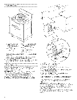
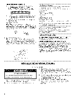
If rangeheighatdjustmeinstnecessaruys,ea wrencohr pliersto loosetnhe4levelinlgegs. Thismaybedonewiththerangoenitsbackorwiththerange supporteodn2 legsaftetrherangehasbeenplacedbackto astandinpgosition. NOTET:oplacerangebackupintoa standinpgositionp,uta sheeot fcardboarodrhardboairndfrontofrangeU. sing2or morepeoples,tandrangebackupontothecardboaordr hardboard. .........I... , _. _--. Tip Over Hazard A child or adult can tip the range and be killed. Connect anti-tip bracket to rear range foot. Reconnect the anti-tip bracket, if the range is moved. Failure to follow these instructions can result in death or serious burns to children and adults. A. Anti-tip bracket B. Mark edge of range C. 1s/_6("2.4 cm) 4. Drill two %" (3.0 mm) holes that correspond to the bracket holes of the determined mounting method. See below. Floor Mounting A B 2. Adjust the leveling legs to the correct height. Leveling legs can be loosened to add up to a maximum of 1" (2.5 cm). A minimum of 3_6" (5.0 mm) is needed to engage the anti-tip bracket. NOTE: If height adjustment is made when range is standing, tilt the range back to adjust the front legs, then tilt forward to adjust the rear legs. 3. When the range is at the correct height, check that there is adequate clearance under the range for the anti-tip bracket. Before sliding range into its final position, check that the antitip bracket will slide under the range and onto the rear leveling leg prior to anti-tip bracket installation. Wall Mounting A. #12x 1%" screws B. Anti-tip bracket f. Remove the anti-tip bracket that is taped inside the upper oven with the literature package. 2. Determine which mounting method to use: floor or wall. If you have a stone or masonry floor you can use the wall mounting method. 3. Determine and mark edge of range in the cutout space. The mounting bracket can be installed on either the left side or right side of the cutout. Position mounting bracket in cutout so that right (or left) edge of the bracket is _%6"(2.4 cm) from the marked edge of the range, as shown. A A. #12x 1s/8'' screws B. Anti-tip bracket 5= Using the Phillips screwdriver, mount anti-tip bracket to the wall or floor with the two #12 x 1%" screws provided.
-
 1
1 -
 2
2 -
 3
3 -
 4
4 -
 5
5 -
 6
6 -
 7
7 -
 8
8 -
 9
9 -
 10
10 -
 11
11 -
 12
12 -
13
-
14
-
15
-
16
-
17
-
18
-
19
-
20
-
21
-
22
-
23
-
24
-
25
-
26
-
27
-
28
-
29
-
30
-
31
-
32
-
33
-
34
-
35
-
36
 |
 |
