Kenwood VR-5900 User Manual - Page 10
What’s on the Front Panel of Your Kenwood Audio-Video Receiver?, MULTI CONTROL Up/Down buttons
 |
View all Kenwood VR-5900 manuals
Add to My Manuals
Save this manual to your list of manuals |
Page 10 highlights
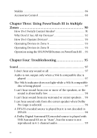
What's on the Front Panel of Your Kenwood Audio-Video Receiver? 2 1 25 24 23 22 21 20 19 DTS-ES DISCRETE 6.1 MATRIX 6.1 NEO : 6 PRO LOGIC SURROUND BACK CD 2 / TAPE 2 CLIP 96kfs MONITOR INDICATOR STANDBY POWER ON/STANDBY PHONES THX DOLBY DIGITAL DTS MPEG D.R.I.V.E. HDCD VOLUME CONTROL ¤ INPUT SELECTOR ‹ DOOR OPEN/CLOSE DOWN UP S VIDEO AV - AUX VIDEO L - AUDIO - R 18 17 16 Buttons behind the door 3 A SPEAKERS B INPUT CD 2/TAPE 2 LISTEN MODE MONITOR MODE THX SOUND RF RF BAND DISPLAY ON/OFF SET UP fi % MULTI CONTROL fi % P.CALL MEMORY AUTO BAND 4 6 8 10 11 12 14 5 79 13 15 1. STANDBY indicator 2. POWER ON/STANDBY button 3. PHONES jack 4. SPEAKERS A/B buttons 5. INPUT MODE button / RF ON/OFF button 6. CD 2/TAPE 2 MONITOR button / RF BAND button 7. LISTEN MODE button/DISPLAY button 8. THX button 9. SOUND button/SET UP button 10. MULTI CONTROL (Up/Down) buttons 11. P. CALL (Up/Down) buttons 12. MEMORY button 13. AUTO button 14. BAND button 15. AV AUX input jacks 16. DOOR OPEN/CLOSE button 17. VOLUME CONTROL knob 18. INPUT SELECTOR buttons 19. Indicators SURROUND BACK 96kfs CD2/TAPE2 MONITOR CLIP INDICATOR 20. Indicators THX DTS D. R. I. V. E. DOLBY DIGITAL MPEG HDCD 21. Display 22. 2-way communication indicator 23. Infrared remote sensor 24. Indicators DTS-ES DISCRETE 6.1 DTS-ES MATRIX 6.1 NEO : 6 PRO LOGIC 25. Infrared remote transmitter Buttons 4 to 14 are located behind the door. Standby mode While the standby indicator of the unit is lit, a small amount of current is flowing into the unit's internal circuitry to back up the memory. This condition is referred to as the standby mode of the unit. While the unit is in the standby mode, it can be turned ON from the remote control unit. 2
-
 1
1 -
2
-
3
-
4
-
 5
5 -
 6
6 -
 7
7 -
 8
8 -
 9
9 -
 10
10 -
 11
11 -
 12
12 -
 13
13 -
 14
14 -
 15
15 -
16
-
17
-
18
-
19
-
20
-
21
-
22
-
23
-
24
-
25
-
26
-
27
-
28
-
29
-
30
-
31
-
32
-
33
-
34
-
35
-
36
-
37
-
38
-
39
-
40
-
41
-
42
-
43
-
44
-
45
-
46
-
47
-
48
-
49
-
50
-
51
-
52
-
53
-
54
-
55
-
56
-
57
-
58
-
59
-
60
-
61
-
62
-
63
-
64
-
65
-
66
-
67
-
68
-
69
-
70
-
71
-
72
-
73
-
74
-
75
-
76
-
77
-
78
-
79
-
80
-
81
-
82
-
83
-
84
-
85
-
86
-
87
-
88
-
89
-
90
-
91
-
92
-
93
-
94
-
95
-
96
-
97
-
98
-
99
-
100
-
101
-
102
-
103
-
104
-
105
-
106
-
107
-
108
-
109
-
110
-
111
-
112
-
113
-
114
-
115
-
116
-
117
-
118
 |
 |
