KitchenAid KBFO42FTX Installation Guide - Page 25
Adjust Doors
 |
UPC - 883049033983
View all KitchenAid KBFO42FTX manuals
Add to My Manuals
Save this manual to your list of manuals |
Page 25 highlights
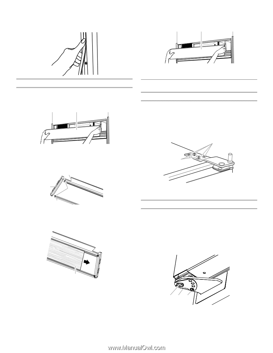
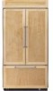
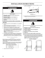
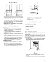
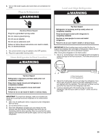
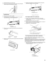
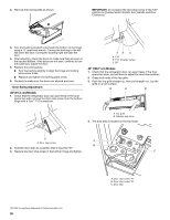
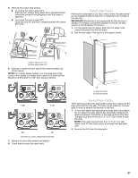
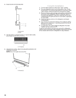
4. Reinstall the trims and corner caps. 5. Remove the protective skin from the screw covers. Snap the screw covers into the handle trim section. 5. Replace the top grille in the cabinet side trims and pull the panel down slightly to lock it into place. B A B Top Grille Panel 1. Grasp both ends of the top grille. 2. Push straight up; then pull straight out. Place the top grille panel-side down on a soft working surface. B A B A. Top grille B. Cabinet side trims 3. Remove one end cap by loosening the nuts and sliding the end cap off. A A. Top grille B. Cabinet side trims Adjust Door(s) Door Alignment (36" [91.4 cm] Models) 1. Loosen, but do not remove, the four Torx®† 27 flat-head mounting screws and the two ¹⁄₄" hex-head mounting screws in the top hinge. 2. Adjust the top hinge of the door to align it. 3. Tighten the Torx®† 27 flat-head mounting screws to a torque of approximately 100 inch-pounds (11.3 Nm). 4. Tighten the ¹⁄₄" hex-head screws. A B C B D A. Bottom rail B. Nuts C. End cap D. Top rail 4. Slide the custom panel into the top grille channel and reattach the end cap. A. Torx®† 27 flat-head mounting screws B. ¹⁄₄" hex-head mounting screws Door Height Adjustment (42" [106.7 cm] Models) Use the following steps to adjust the door height, up or down, after the refrigerator has been leveled. NOTE: Adjust the right door to the position of the left door first. If it is necessary to adjust the left door, you must make sure that the hinged center rail located on the left-hand door does not drag when closing the door. 1. Open the freezer drawer. Remove the locking plate screw from the bottom side of the refrigerator door hinge using a ¹⁄₄" open-end wrench. A A. Custom panel ABC A. Bushing B. Locking plate C. Locking plate screw 25
-
 1
1 -
2
-
3
-
4
-
5
-
6
-
7
-
8
-
9
-
10
-
11
-
12
-
13
-
14
-
15
-
16
-
17
-
18
-
19
-
 20
20 -
 21
21 -
 22
22 -
 23
23 -
 24
24 -
 25
25 -
 26
26 -
 27
27 -
 28
28 -
 29
29 -
 30
30 -
31
-
32
-
33
-
34
-
35
-
36
-
37
-
38
-
39
-
40
-
41
-
42
-
43
-
44
-
45
-
46
-
47
-
48
-
49
-
50
-
51
-
52
-
53
-
54
-
55
-
56
-
57
-
58
-
59
-
60
-
61
-
62
-
63
-
64
-
65
-
66
-
67
-
68
-
69
-
70
-
71
-
72
-
73
-
74
-
75
-
76
-
77
-
78
-
79
-
80
-
81
-
82
-
83
-
84
 |
 |