KitchenAid KGCU463VSS Installation Guide - Page 13
On Griddle Models
 |
UPC - 883049155975
View all KitchenAid KGCU463VSS manuals
Add to My Manuals
Save this manual to your list of manuals |
Page 13 highlights
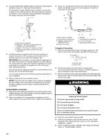
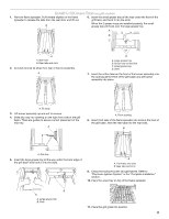
On Griddle Models: Support the control console in the middle with one arm and disconnect the griddle switch connectors and the grill indicator light with the other hand. 13. When finished adjusting the flame height, put a control knob back onto the valve stem and turn off the burner. 14. Remove the control knob. 15. Replace the round gasket. 16. Repeat steps 8 through 15 for any other burners that need adjustment. 17. Reinstall the control console. Support the control console in the middle with one arm and reconnect the griddle switch connectors and/or grill indicator light connector. 18. Set the control console back into place on the cooktop. For a proper fit, the flange of the control console must hook over the lip on the front of the cooktop. B A A. Grill indicator light connector B. Griddle switch connectors 7. Remove console and set aside. 8. Remove the round gasket from the valve stem. 9. Put a control knob onto the valve stem of the burner you want to adjust. A B A. Control console flange B. Front lip of cooktop 19. Check that the control console is flush with the top edge of the cooktop. 10. Using a butane extension lighter, turn the control knob to LO and light the burner. 11. Remove the control knob. 12. Use a ¹⁄₈" x 4¼" flat-blade screwdriver to adjust the flame height. Tighten screw to reduce flame height. Loosen screw to increase flame height. NOTE: When you are converting to LP gas, the screw should be tightened down completely. A A. Flush with top of cooktop 20. Replace the 2 screws on each side of the control console. 21. Push the cooktop back into place in the cutout. 22. Replace the control knobs. 23. Replace burner grates. 24. Plug in cooktop or reconnect power. 25. Test the flame by turning the control from LO to HI, checking the flame at each setting. A B A. Single flame burner adjustment screw (on right side of valve) B. Dual flame burner adjustment screw (on left side of valve) 13
-
 1
1 -
2
-
3
-
4
-
5
-
6
-
7
-
 8
8 -
 9
9 -
 10
10 -
 11
11 -
 12
12 -
 13
13 -
 14
14 -
 15
15 -
 16
16 -
 17
17 -
 18
18 -
19
-
20
-
21
-
22
-
23
-
24
-
25
-
26
-
27
-
28
-
29
-
30
-
31
-
32
-
33
-
34
-
35
-
36
-
37
-
38
-
39
-
40
 |
 |
