KitchenAid KGRS505XSS Installation Guide - Page 7
Adjust Leveling Legs, Install Anti-Tip Bracket
 |
UPC - 883049199481
View all KitchenAid KGRS505XSS manuals
Add to My Manuals
Save this manual to your list of manuals |
Page 7 highlights
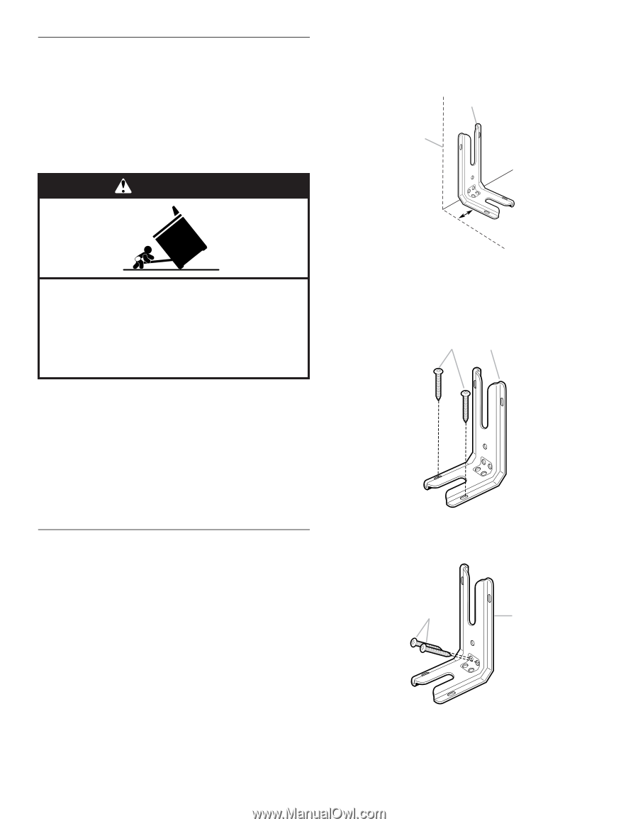
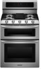
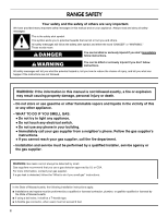
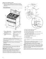
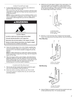
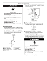
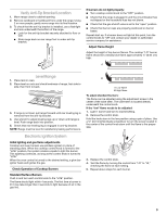
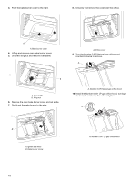
Adjust Leveling Legs 1. If range height adjustment is necessary, use a wrench or pliers to loosen the 4 leveling legs. This may be done with the range on its back or with the range supported on 2 legs after the range has been placed back to a standing position. NOTE: To place range back up into a standing position, put a sheet of cardboard or hardboard in front of range. Using 2 or more people, stand range back up onto the cardboard or hardboard. WARNING 3. Determine and mark edge of range in the cutout space. The mounting bracket can be installed on either the left side or right side of the cutout. Position mounting bracket in cutout so that right (or left) edge of the bracket is 2.4 cm) from the marked edge of the range, as shown. A B C Tip Over Hazard A child or adult can tip the range and be killed. Connect anti-tip bracket to rear range foot. Reconnect the anti-tip bracket, if the range is moved. Failure to follow these instructions can result in death or serious burns to children and adults. A. Anti-tip bracket B. Mark edge of range. C 2.4 cm) 4. Drill two ¹⁄₈" (3.0 mm) holes that correspond to the bracket holes of the determined mounting method. See the following. Floor Mounting A B 2. Adjust the leveling legs to the correct height. Leveling legs can be loosened to add up to a maximum of 1" (2.5 cm). A minimum of 5.0 mm) is needed to engage the anti-tip bracket. NOTE: If height adjustment is made when range is standing, tilt the range back to adjust the front legs, then tilt forward to adjust the rear legs. 3. When the range is at the correct height, check that there is adequate clearance under the range for the anti-tip bracket. Before sliding range into its final location, check that the antitip bracket will slide under the range and onto the rear leveling leg prior to anti-tip bracket installation. Install Anti-Tip Bracket 1. Remove the anti-tip bracket that is taped inside the upper oven with the package containing literature. 2. Determine which mounting method to use: floor or wall. If you have a stone or masonry floor you can use the wall mounting method. Wall Mounting A. #12 x 1⁵⁄₈" screws B. Anti-tip bracket A B A. #12 x 1⁵⁄₈" screws B. Anti-tip bracket 5. Using a Phillips screwdriver, mount anti-tip bracket to the wall or floor with the two #12 x 1⁵⁄₈" screws provided. 7
-
 1
1 -
 2
2 -
 3
3 -
 4
4 -
 5
5 -
 6
6 -
 7
7 -
 8
8 -
 9
9 -
 10
10 -
 11
11 -
 12
12 -
13
-
14
-
15
-
16
-
17
-
18
-
19
-
20
-
21
-
22
-
23
-
24
-
25
-
26
-
27
-
28
-
29
-
30
-
31
-
32
-
33
-
34
-
35
-
36
-
37
-
38
-
39
-
40
 |
 |