KitchenAid KUWL304CSS Use & Care Guide - Page 7
Drain Pump Installation, Rear Panel, Drain Tube, Parts Locations, Drain Pump Mounting Tab Slot
 |
View all KitchenAid KUWL304CSS manuals
Add to My Manuals
Save this manual to your list of manuals |
Page 7 highlights
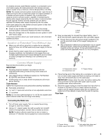
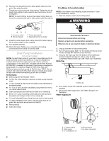
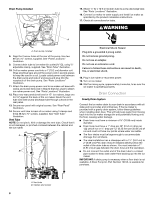
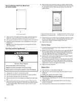
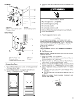
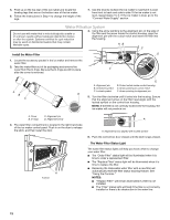
Drain Pump Installation Parts Locations NOTE: Do not kink, smash or damage tubes or wires during installation. A 1. Unplug ice maker or disconnect power. B 2. Remove rear panel. See "Rear Panel" illustration for 5 screw locations. Pull rear panel away from the drain tube and discard. Rear Panel C A D E A A. Screw locations 3. Remove the old drain tube and clamp attached to the ice maker bin. NOTE: Discard old drain tube and clamp. 4. Install new drain tube ID x 5¹⁄₈") from ice maker bin to drain pump reservoir inlet using new adjustable clamps. See "Drain Tube" illustration. NOTES: ■ Do not kink. ■ Trim tube length, if required. Drain Tube G F A. Vent tube B hose clamp C. Drain pump discharge tube D. Drain pump E. Ice maker unit power cord F. #8-32 x ³⁄₈" pump mounting screws G. Drain pump power cord, clamp and screw 6. Remove power cord clamp and ground screw attached to ice maker power cord, which is mounted to the unit base. See "Parts Locations" illustration. NOTE: Clamp and screw will be reused. 7. Slide drain pump into the ice maker base on the right side. The pump mounting tab should slip into the rectangular slot in the ice maker base. It will be necessary to tip the pump slightly to slip into the slot. See "Drain Pump Mounting Tab Slot" illustration. Drain Pump Mounting Tab Slot A B C D A adjustable hose clamp B. Drain tube (ice bin to drain pump) C adjustable hose clamp D. Drain pump reservoir inlet 5. Install vent tube ID x 32" [81 cm]) to drain pump reservoir vent. Use one ⁵⁄₈" small adjustable clamp, supplied. See "Parts Locations" illustration. NOTE: Do not install household drain tube at this time. A A. Mounting tab slot 7
-
 1
1 -
 2
2 -
 3
3 -
 4
4 -
 5
5 -
 6
6 -
 7
7 -
 8
8 -
 9
9 -
 10
10 -
 11
11 -
 12
12 -
13
-
14
-
15
-
16
-
17
-
18
-
19
-
20
-
21
-
22
-
23
-
24
-
25
-
26
-
27
-
28
-
29
-
30
-
31
-
32
-
33
-
34
-
35
-
36
-
37
-
38
-
39
-
40
-
41
-
42
-
43
-
44
-
45
-
46
-
47
-
48
-
49
-
50
-
51
-
52
-
53
-
54
-
55
-
56
-
57
-
58
-
59
-
60
-
61
-
62
-
63
-
64
-
65
-
66
-
67
-
68
 |
 |
