LG ARUB115BT2 Service Manual
LG ARUB115BT2 Manual
 |
View all LG ARUB115BT2 manuals
Add to My Manuals
Save this manual to your list of manuals |
LG ARUB115BT2 manual content summary:
- LG ARUB115BT2 | Service Manual - Page 1
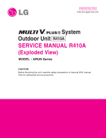
Internal Use Only http://biz.lgservice.com System Outdoor Unit R410A SERVICE MANUAL R410A (Exploded View) MODEL : ARUN Series CAUTION Before Servicing the unit, read the safety precautions in General SVC manual. Only for authorized service personnel. - LG ARUB115BT2 | Service Manual - Page 2
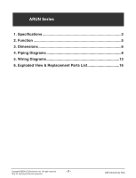
ARUN Series 1. Specifications 3 2. Function 5 3. Dimensions 6 4. Piping Diagrams 8 5. Wiring Diagrams 13 6. Exploded View & Replacement Parts List 16 Copyright ©2008 LG Electronics. Inc. All right reserved. Only for training and service purposes -2- LGE Internal Use Only - LG ARUB115BT2 | Service Manual - Page 3
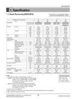
12.5 Combination Unit ARUB076BT2 ARUB096BT2 ARUB115BT2 ARUB154BT2 Independent Unit ARUB076BT2 ARUB096BT2 ARUB115BT2 ARUB076BT2 ARUB076BT2 kW 22.4 .3 l/s = CMM x 1000/60 Copyright ©2008 LG Electronics. Inc. All right reserved. Only for training and service purposes -3- LGE Internal Use Only - LG ARUB115BT2 | Service Manual - Page 4
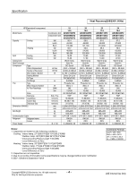
285 628+628 CVV-SB 1.25x2C R410A EEV 3, 208/230, 60 24 19.0 ARUB230BT2 ARUB115BT2 ARUB115BT2 67.2 57,800 229,300 75.6 65,000 258,000 21.60 22.20 Warm .3 l/s = CMM x 1000/60 Copyright ©2008 LG Electronics. Inc. All right reserved. Only for training and service purposes -4- LGE Internal Use Only - LG ARUB115BT2 | Service Manual - Page 5
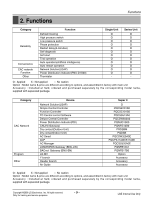
(BNU-LW) BACnet Gateway (BNU-BN) LG MV Y branch Header branch Air Guide Super II O PQCSB101S0 PQCSC101S0 PQCSS513A0 PQCSW502A2 PQNUD1S00 supplied with separated package. Copyright ©2008 LG Electronics. Inc. All right reserved. Only for training and service purposes -5- LGE Internal Use Only - LG ARUB115BT2 | Service Manual - Page 6
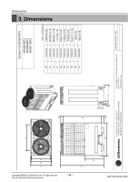
Dimensions 3. Dimensions Copyright ©2008 LG Electronics. Inc. All right reserved. Only for training and service purposes L3 L2 D Outdoor Unit(208/230V) ARUB076BT2 L4 ARUB096BT2 ARUB115BT2 L6 [Unit: mm(inch)] W mm(inch) 1280(50-3/8) H mm(inch) 1607(63-5/16) D mm(inch) 730(28-11/16 - LG ARUB115BT2 | Service Manual - Page 7
Copyright ©2008 LG Electronics. Inc. All right reserved. Only for training and service purposes L4 L5 L3 L2 D L7 H L1 The Units should be installed to leave sufficient space in front for the on site refrigerant piping work to be carried out comfortably. 250mm (9-13/16 inch) or more 250mm - LG ARUB115BT2 | Service Manual - Page 8
Piping Diagrams 4.1 Heat Pump Model 4.1.1 ARUB076BT2, ARUB096BT2, ARUB115BT2 Cooling Operation Indoor unit Heat Exch. EEV Fan Filter valve EEV Sensor s Solenoid Outdoor unit Service Valve Strainer *( ) To be used only for series Copyright ©2008 LG Electronics. Inc. All right reserved. Only - LG ARUB115BT2 | Service Manual - Page 9
Gas Pipe Liquid Pipe INV Comp Accum CON Comp Liquid Injection Sub-Cooler Pressure sensor Pressure switch Check valve EEV Sensor s Solenoid Outdoor unit Service Valve Strainer *( ) To be used only for series Copyright ©2008 LG Electronics. Inc. All right reserved. Only for training and - LG ARUB115BT2 | Service Manual - Page 10
Gas Pipe Liquid Pipe INV Comp Accum Liquid Injection CON Comp Sub-Cooler Pressure sensor Pressure switch Check valve EEV Sensor s Solenoid Outdoor unit Service Valve Strainer *( ) To be used only for series Copyright ©2008 LG Electronics. Inc. All right reserved. Only for training and - LG ARUB115BT2 | Service Manual - Page 11
By pass O/S High Pressure Gas Pipe Low Pressure Gas Pipe Liquid Pipe CON Comp Outdoor unit Pressure sensor Pressure switch Check valve EEV Sensor s Solenoid Service Valve Strainer Copyright ©2008 LG Electronics. Inc. All right reserved. Only for training and - LG ARUB115BT2 | Service Manual - Page 12
Gas Bypass O/S High Pressure Gas Pipe Low Pressure Gas Pipe Liquid Pipe CON Comp Outdoor unit Pressure sensor Pressure switch Check valve EEV Sensor s Solenoid Service Valve Strainer Copyright ©2008 LG Electronics. Inc. All right reserved. Only for training and - LG ARUB115BT2 | Service Manual - Page 13
5. Wiring Diagrams 5.1 Heat Pump Model 5.1.1 3Ø 208/230V(ARUB076BT2, ARUB096BT2, ARUB115BT2) Wiring Diagrams 3Ø 208/230V 3N 60Hz Copyright ©2008 LG Electronics. Inc. All right reserved. Only for training and service purposes - 13 - LGE Internal Use Only - LG ARUB115BT2 | Service Manual - Page 14
SENSOR 2) CN35 AIR (OUTDOOR TEMPERATURE SENSOR) SUCTION (SUCTION TEMPERATURE SENSOR) DISCHARGE(C) (CONST COMP DISCHARGE TEMP SENSOR) CN30 P-SENSOR(H) (HIGH PRESSURE SENSOR) Copyright ©2008 LG Electronics. Inc. All right reserved. Only for training and service purposes - 14 - LGE Internal Use Only - LG ARUB115BT2 | Service Manual - Page 15
CN_L1(R) R Phase Terminal CN_L2(S) S Phase Terminal CN_L3(T) T Phase Terminal CN-FLASH WRITE(INV) CN05 COOLING FAN CN01 FAN Communication Terminal to Fan PCB Copyright ©2008 LG Electronics. Inc. All right reserved. Only for training and service purposes - 15 - LGE Internal Use Only - LG ARUB115BT2 | Service Manual - Page 16
Explodede View 6. Exploded View Outdoor Unit UW1 Chassis (208/230V, ARUB076BT2/096BT2/115BT2) 268711C 268711B 649950A 268711A 566001 649950B W6631A W6200 W6640 W6631B Copyright ©2008 LG Electronics. Inc. All right reserved. Only for training and service purposes - 16 - LGE Internal Use Only - LG ARUB115BT2 | Service Manual - Page 17
Liquid Pipe + sub Cooler IN + Sub Cooler OUT Inv. discharge + HEX(Front) + HEX (back) Air + suction Pipe Copyright ©2008 LG Electronics. Inc. All right reserved. Only for training and service purposes - 17 - Housing color : yellow Housing color : purple Housing color : black LGE Internal Use Only - LG ARUB115BT2 | Service Manual - Page 18
P/NO : MFL54555502 JUNE, 2008
-
 1
1 -
 2
2 -
 3
3 -
 4
4 -
 5
5 -
 6
6 -
 7
7 -
8
-
9
-
10
-
11
-
12
-
13
-
14
-
15
-
16
-
17
-
18
 |
 |
System
Outdoor Unit
SERVICE MANUAL R410A
(Exploded View)
MODEL : ARUN Series
CAUTION
Before Servicing the unit, read the safety precautions in General SVC manual.
Only for authorized service personnel.
Internal Use Only
R410A