LG ARUB115BT2 Service Manual - Page 15
Noize Filter, Inveter PCB 3, FAN PCBUW1
 |
View all LG ARUB115BT2 manuals
Add to My Manuals
Save this manual to your list of manuals |
Page 15 highlights
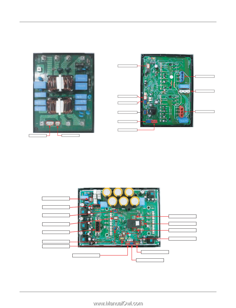
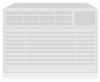
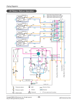
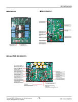
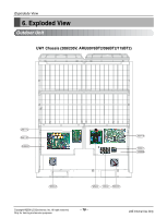
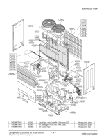
I Noize Filter I FAN PCB(UW1) Wiring Diagrams TO MAIN PCB 220V Power Output Terminal TO INV. PCB 220V Power Output Terminal CN_MICOM WRITING INV Onboarding Terminal CN HEAT SINK Heat Sink Temp. Sensor CN INV_COM Communication Terminal to INV PCB CN 15V DC 15V Power Input Terminal CN HALL SENSOR(R) Left Fan Motor Hall Sensor CN HALL SENSOR(L) Right Fan Motor Hall Sensor CN FAN RIGHT Left Fan Motor Hall Sensor CN DC LINK 700V DC LINK CN FAN LEFT Right Fan Motor Hall Sensor I Inveter PCB (3Ø 208/230V) CN_06AC220V INPUT 220V Power Input Terminal CN12 DC_LINK(700V) (700V DC LINK) CN13 15V OUTPUT DC 15V Output Terminal CN04 PFC LGMV PFC Onboarding Terminal CN14 UVW OUT UVW Output Terminal CN-FLASH WRITE(PFC) CN03 INV LGMV INV Onboarding Terminal CN02 Main Communication Terminal to Main PCB CN_L1(R) R Phase Terminal CN_L2(S) S Phase Terminal CN_L3(T) T Phase Terminal CN-FLASH WRITE(INV) CN05 COOLING FAN CN01 FAN Communication Terminal to Fan PCB Copyright ©2008 LG Electronics. Inc. All right reserved. Only for training and service purposes - 15 - LGE Internal Use Only
-
 1
1 -
2
-
3
-
4
-
5
-
6
-
7
-
8
-
9
-
 10
10 -
 11
11 -
 12
12 -
 13
13 -
 14
14 -
 15
15 -
 16
16 -
 17
17 -
 18
18
 |
 |