LG ARUB115BT2 Service Manual - Page 8
Arub076bt2, Arub096bt2, Arub115bt2
 |
View all LG ARUB115BT2 manuals
Add to My Manuals
Save this manual to your list of manuals |
Page 8 highlights
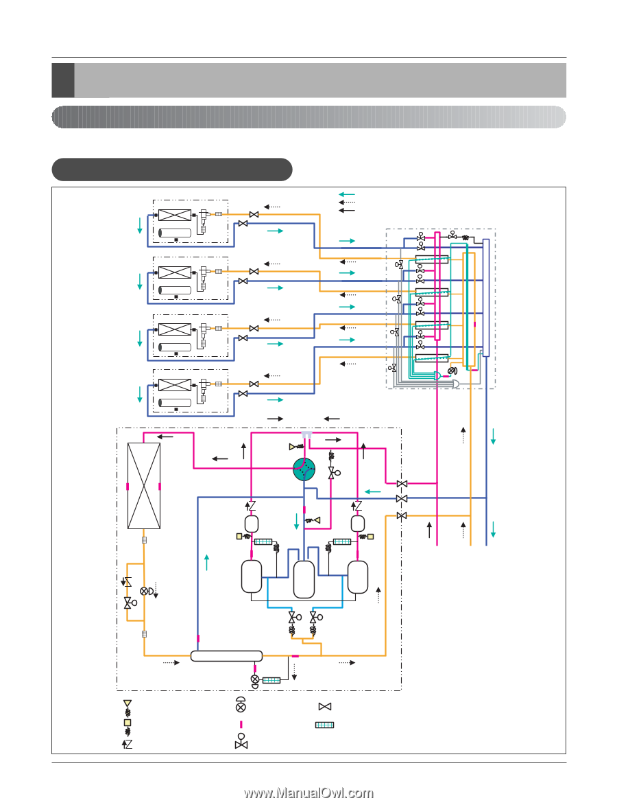
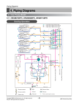
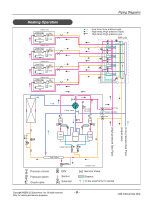
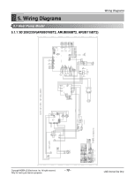
Piping Diagrams 4. Piping Diagrams 4.1 Heat Pump Model 4.1.1 ARUB076BT2, ARUB096BT2, ARUB115BT2 Cooling Operation Indoor unit Heat Exch. EEV Fan Filter Indoor unit Heat Exch. EEV Fan Filter Indoor unit Heat Exch. EEV Fan Filter : Low temp./Low pressure gas : High temp./High pressure liquid : High temp./High pressure gas HR unit s s s s s s s s s s s s s Indoor unit Heat Exch. EEV Fan Filter (Low pressure Gas Pipe) (Liquid pipe) (High pressure Gas Pipe) s s s s 4 Way Valve O/S Hot Gas By pass O/S High Pressure Gas Pipe Low Pressure Gas Pipe Liquid Pipe INV Comp Accum Liquid Injection CON Comp Sub-Cooler Pressure sensor Pressure switch Check valve EEV Sensor s Solenoid Outdoor unit Service Valve Strainer *( ) To be used only for series Copyright ©2008 LG Electronics. Inc. All right reserved. Only for training and service purposes -8- LGE Internal Use Only
-
 1
1 -
2
-
 3
3 -
 4
4 -
 5
5 -
 6
6 -
 7
7 -
 8
8 -
 9
9 -
 10
10 -
 11
11 -
 12
12 -
 13
13 -
14
-
15
-
16
-
17
-
18
 |
 |