LG ARUB115BT2 Service Manual - Page 10
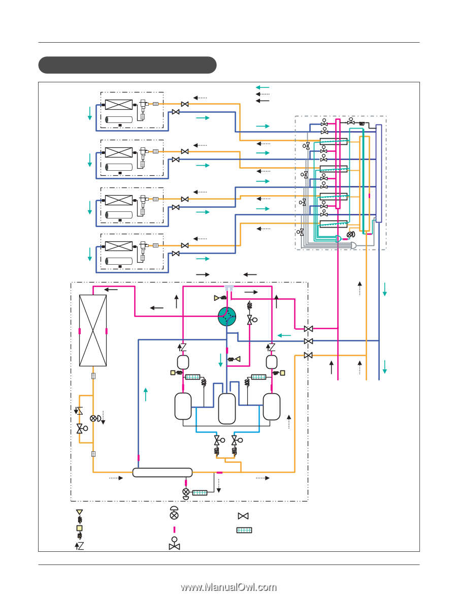
Oil Return/ Defrost Operation
 |
View all LG ARUB115BT2 manuals
Add to My Manuals
Save this manual to your list of manuals |
Page 10 highlights
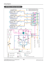
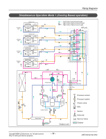
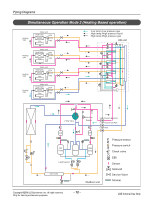
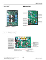
Piping Diagrams Oil Return/ Defrost Operation Indoor unit Heat Exch. EEV Fan Filter Indoor unit Heat Exch. EEV Fan Filter Indoor unit Heat Exch. EEV Fan Filter Indoor unit Heat Exch. EEV Fan Filter s : Low temp./Low pressure gas : High temp./High pressure liquid : High temp./High pressure gas HR unit s s s s s s s s s s s s (Low pressure Gas Pipe) (Liquid pipe) (High pressure Gas Pipe) s s s s 4 Way Valve O/S Hot Gas By pass O/S High Pressure Gas Pipe Low Pressure Gas Pipe Liquid Pipe INV Comp Accum Liquid Injection CON Comp Sub-Cooler Pressure sensor Pressure switch Check valve EEV Sensor s Solenoid Outdoor unit Service Valve Strainer *( ) To be used only for series Copyright ©2008 LG Electronics. Inc. All right reserved. Only for training and service purposes - 10 - LGE Internal Use Only
-
 1
1 -
2
-
3
-
4
-
 5
5 -
 6
6 -
 7
7 -
 8
8 -
 9
9 -
 10
10 -
 11
11 -
 12
12 -
 13
13 -
 14
14 -
 15
15 -
16
-
17
-
18
 |
 |