LG BG-101A Service Manual
LG BG-101A Manual
 |
View all LG BG-101A manuals
Add to My Manuals
Save this manual to your list of manuals |
LG BG-101A manual content summary:
- LG BG-101A | Service Manual - Page 1
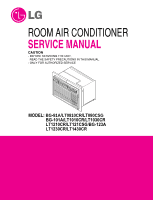
ROOM AIR CONDITIONER SERVICE MANUAL CAUTION - BEFORE SERVICING THE UNIT, READ THE SAFETY PRECAUTIONS IN THIS MANUAL. - ONLY FOR AUTHORIZED SERVICE MODEL: BG-81A/LT0810CR/LT080CSG BG-101A/LT1010CR/LT1030CR LT1210CR/LT121CSG/BG-123A LT1230CR/LT1430CR - LG BG-101A | Service Manual - Page 2
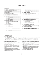
20 4.3 TROUBLESHOOTING GUIDE 21 5. SCHEMATIC DIAGRAM 5.1 CIRCUIT DIAGRAM 27 6. EXPLODED VIEW 27 7. REPLACEMENT PARTS LIST .......28 1. PREFACE This SERVICE MANUAL provides various service information, including the mechanical and electrical parts etc. This room air conditioner was manufactured - LG BG-101A | Service Manual - Page 3
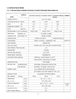
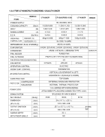
ROOM TEMP. CONTROL AIR DIRECTION CONTROL CONSTRUCTION PROTECTOR COMPRESSOR FAN MOTOR POWER CORD DRAIN SYSTEM NET WEIGHT (lbs/kg) DIMENSION (inch) (W x H x D) (mm) SLEEVE DIMESION (inch) (W x H x D) (mm) SLEEVE DEPTH (inch) WITH FRONT GRILLE (mm) BG-101A/LT1010CR LT121CSG/LT1210CR - LG BG-101A | Service Manual - Page 4
1.3.2 FOR LT1030CR/LT1230CR/BG-123A/LT1430CR ITEMS MODELS LT1030CR LT1230CR/BG-123A LT1430CR REMAR POWER SUPPLY 1Ø, 230/208V, 60Hz 6 POLES 4POLES 4POLES OPERATION CONTROL ELECTRIC ROOM TEMP. CONTROL THERMISTOR AIR DIRECTION CONTROL VERTICAL LOUVER(RIGHT & LEFT) HORIZONTAL LOUVER(UP & - LG BG-101A | Service Manual - Page 5
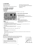
service. 1.5 CONTROL LOCATIONS 1.5.1 COOLING ONLY MODEL • OPERATION • Side air-intake, side cooled-air • To turn the air conditioner ON, push this button. To turn the air conditioner OFF, push the of hours until shut-off. • For your sleeping comfort, once Time is set, the Temperature setting will - LG BG-101A | Service Manual - Page 6
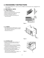
2. DISASSEMBLY INSTRUCTIONS - Prior to disassembling the unit, make sure that the POWER is off procedure. (See Fig. 3) (Refer to the circuit diagram found on pages 26 in this manual and on the control box.) Figure 2 Figure 3 -6- ESnaevCregoryol Fan MODE Timer TIMER FF3F2H1MILGEOHDW TEMP - LG BG-101A | Service Manual - Page 7
2.2 AIR HANDLING PARTS 2.2.1 ORIFICE, AND TURBO FAN 1. Remove the front grille. (Refer to section 2.1.1) 2. Remove the cabinet. (Refer to section 2.1.2) 3. Remove the 2 screws which fasten the - LG BG-101A | Service Manual - Page 8
valve to attach the recovery system to, install one (such as a WATCO A-1) before venting the FreonTM . Leave the valve in place after servicing the system. 3. Disconnect the 3 leads from the compressor. 4. After purging the unit completely, unbraze the suction and discharge tubes at the compressor - LG BG-101A | Service Manual - Page 9
2.3.4 POWER CORD 1. Remove the control box. (Refer to section 2.1.3) 2. Unfold the control box. (Refer to section 2.3.3) 3. Disconnect the grounding screw from the Base pan. 4. Disconnect 2 receptacles. 5. Remove a screw which fastens the clip cord. 6. Pull the power cord. (See Fig. 13) 7. Re- - LG BG-101A | Service Manual - Page 10
valve to attach the recovery system, install one (such as a WATCO A-1) before venting the FreonTM. Leave the valve in place after servicing the system. 2.4.1 CONDENSER 1. Remove the cabinet. (Refer to section 2.1.2) 2. Remove the brace. (Refer to section 2.2.1) 3. Remove the 7 screws which fasten - LG BG-101A | Service Manual - Page 11
A-1) before venting the FreonTM. Leave the valve in place after servicing the system. 2. After discharging the unit completely, remove the desired component, ports, leaving the valves open. 4. Solder the pinch-off tubes with Service valves. 5. Evacuate as follows. 1) Connect the vacuum pump, as illustrated - LG BG-101A | Service Manual - Page 12
, Brazing equipment. Pinch-off tool capable of making a vapor-proof seal, Leak detector, Tubing cutter, Hand Tools to remove components, Service valve. CONDENSER (HIGH PRESSURE SIDE) COMPOUND GAUGE MANIFOLD GAUGE B A CAPILLARY TUBE SEE INSETS BELOW EVAPORATOR (LOW PRESSURE SIDE) COMPRESSOR - LG BG-101A | Service Manual - Page 13
in this manual pose an excessive weight hazard. Two or more people are needed to move and install the unit. To prevent injury or strain, use proper lifting and carrying techniques when moving unit. • Carefully inspect location where air conditioner will be installed. Be sure it will support the - LG BG-101A | Service Manual - Page 14
will lessen the chance that service will be needed. ITEMS IN Plastic grille Vertical insulation strip Around Insulation Strips Horizontal Insulation Strip Support Block Baffle Shim Trim Frame 263/4 x 161/2 159/16 stop for the Air Conditioner. 2 Remove old air conditioner from existing wall sleeve - LG BG-101A | Service Manual - Page 15
the air conditioner, be careful to avoid cuts from sharp metal fins on front and rear coils. • Make sure air conditioner does not fall during removal. • If unit does not operate after installation check, to be sure the circuit interrupter has not been tripped. Refer to the Troubleshooting guide for - LG BG-101A | Service Manual - Page 16
5 If the depth of your existing wall sleeve is less than or equal to 18", skip to step 7. Otherwise, cut the baffles and the support blocks according to length "A" in the table below. Depth"D" of the existing Length "A" wall sleeve (inches) (inches) 18 D 18-5/8 3/4 18-5/8 D 19-3/4 1-3/4 19 - LG BG-101A | Service Manual - Page 17
the air conditioner, be careful to avoid cuts from sharp metal fins on front and rear coils. • Make sure air conditioner does not fall during removal. • If unit does not operate after installation check, to be sure the circuit interrupter has not been tripped. Refer to the Troubleshooting guide for - LG BG-101A | Service Manual - Page 18
of the existing Length "A" wall sleeve (inches) (inches) 18 D 18-5/8 3/4 A Support Block 18-5/8 D 19-3/4 1-3/4 Baffle 19-3/4 D 22 4 A FIG. 34 Place the from leaving the sleeve. 6 Remove the backing from the support blocks and attach them to the inside of the wall sleeve as shown FIG - LG BG-101A | Service Manual - Page 19
FIG. 36 Shim (2EA) CAUTION • Air conditioners covered in this manual pose an excessive weight hazard. Two or air conditioner does not fall during removal. • If unit does not operate after installation check, to be sure the circuit interrupter has not been tripped. Refer to the Troubleshooting guide - LG BG-101A | Service Manual - Page 20
4. TROUBLESHOOTING GUIDE 4.1 OUTSIDE DIMENSIONS 20-3/32" (499mm) 24" (610mm) Cool Energy Saver and the flow of the refrigerant in the cooling cycle. ROOM AIR CONDITIONER CYCLE OF REFRIGERATION EVAPORATOR COILS COOLED AIR COMPLETE LIQUID BOIL OFF POINT SUCTION LIME COOL LOW PRESSURE VAPOR - LG BG-101A | Service Manual - Page 21
TROUBLESHOOTING GUIDE In general, possible trouble is classified in two causes. The one is called Starting Failure which is caused from an electrical defect, and the other is Ineffective Air of fan Clogged air filter Obstruction at air outlet Stop auto air-swing Correct above troubles Check clogging - LG BG-101A | Service Manual - Page 22
Fails to Start Check power source. Check control switch setting. Only compressor fails to start. Drop in power voltage. Defective compressor capacitor. Check capacitor. Replacement. Improper thermostat setting Loose terminal connection. Improper wiring Check circuit breaker and fuse. Gas leakage - LG BG-101A | Service Manual - Page 23
COMPLAINT Fan motor will not run. Fan motor runs intermittently Fan motor noise. CAUSE No power Power supply cord Rotary switch Wire disconnected or connection loose Capacitor (Discharge capacitor before testing.) Will not rotate Revolves on overload. Grommets Fan Turbo fan Loose set screw Worn - LG BG-101A | Service Manual - Page 24
runs. CAUSE Voltage Wiring Rotary Thermostat Capacitor (Discharge capacitor before servicing.) Compressor Overload REMEDY Check voltage. See the limits on , remove the overload, cool it, and retest.) ROOM AIR CONDITIONER VOLTAGE LIMITS NAME PLATE RATING MINIMUM 115V 103.5V 208/230V 187V MAXIMUM - LG BG-101A | Service Manual - Page 25
noise. Condenser fins (damaged) Capacitor Wiring Refrigerating system Air filter Exhaust damper door Unit undersized Blower or fan or missing, correct. If the blower or fan is hitting air guide, rearrange the air handling parts. Remove the cabinet and carefully rearrange tubing not to contact cabinet, - LG BG-101A | Service Manual - Page 26
5. SCHEMATIC DIAGRAM 5.1 CIRCUIT DIAGRAM • MODEL : BG-101A/LT1010CR/LT121CSG/LT1210CR /LT0810CR/LT080CSG/BG-81A LT1030CR/LT1230CR/BG-123A/LT1430CR -26- - LG BG-101A | Service Manual - Page 27
6. EXPLODED VIEW • MODEL: BG-101A/LT1010CR/LT121CSG/LT1210CR /LT0810CR/LT080CSG/BG-81A LT1030CR/LT1230CR/BG-123A/LT1430CR E 152302 135303 147581 147582-1 132100 359012 W48602 354210 349480 147582-2 135312 346811 352380 149980 131400 559011 435301 435300 554031 731273 A 268711-2 567480 - LG BG-101A | Service Manual - Page 28
PWB(PCB) ASSEMBLY,MAIN MOTOR ASSEMBLY,SINGLE ORIFICE TUBE ASSEMBLY,DISCHARGE SINGLE TUBE ASSEMBLY,EVAPORATOR IN TUBE ASSEMBLY,SUCTION SINGLE AIR GUIDE EVAPORATOR ASSEMBLY,FIRST FAN,TURBO GRILLE ,REAR TUBE ASSEMBLY,CONDENSER OUT DAMPER,COMPRESSOR TUBE,CAPILLARY BENDING CONDENSER ASSEMBLY,BENDING - LG BG-101A | Service Manual - Page 29
• MODEL: BG-81A Location No. 130410 131400 135303 135312 147581 147582-1 147582-2 147900 149980 ORIFICE TUBE ASSEMBLY,DISCHARGE SINGLE TUBE ASSEMBLY,EVAPORATOR IN TUBE ASSEMBLY,SUCTION SINGLE AIR GUIDE EVAPORATOR ASSEMBLY,FIRST FAN,TURBO GRILLE ,REAR TUBE ASSEMBLY,CONDENSER OUT DAMPER,COMPRESSOR - LG BG-101A | Service Manual - Page 30
IN TUBE ASSEMBLY,SUCTION SINGLE AIR GUIDE EVAPORATOR ASSEMBLY,FIRST FAN,TURBO CONDENSER ASSEMBLY,BENDING COMPRESSOR SET FAN ASSEMBLY,AXIAL O.L.P INSTALL PART ASSEMBLY.SINGLE CAPACITOR,DRAWING CLAMP,SPRING GRILLE,REAR FILTER,AIR FRAME Qty 1 1 1 1 1 2 4 1 1 1 1 1 1 1 1 1 1 1 1 1 1 1 1 1 1 1 - LG BG-101A | Service Manual - Page 31
PWB(PCB) ASSEMBLY,MAIN MOTOR ASSEMBLY,SINGLE ORIFICE TUBE ASSEMBLY,DISCHARGE SINGLE TUBE ASSEMBLY,EVAPORATOR IN TUBE ASSEMBLY,SUCTION SINGLE AIR GUIDE EVAPORATOR ASSEMBLY,FIRST FAN,TURBO GRILLE ,REAR TUBE ASSEMBLY,CONDENSER OUT DAMPER,COMPRESSOR TUBE,CAPILLARY BENDING CONDENSER ASSEMBLY,BENDING - LG BG-101A | Service Manual - Page 32
• MODEL: BG-101A Location No. 130410 131400 135303 135312 147581 147582-1 147582-2 149980 237200 238310 ORIFICE TUBE ASSEMBLY,DISCHARGE SINGLE TUBE ASSEMBLY,EVAPORATOR IN TUBE ASSEMBLY,SUCTION SINGLE AIR GUIDE EVAPORATOR ASSEMBLY,FIRST FAN,TURBO GRILLE ,REAR TUBE ASSEMBLY,CONDENSER OUT DAMPER, - LG BG-101A | Service Manual - Page 33
PWB(PCB) ASSEMBLY,MAIN MOTOR ASSEMBLY,SINGLE ORIFICE TUBE ASSEMBLY,DISCHARGE SINGLE TUBE ASSEMBLY,EVAPORATOR IN TUBE ASSEMBLY,SUCTION SINGLE AIR GUIDE EVAPORATOR ASSEMBLY,FIRST FAN,TURBO GRILLE ,REAR TUBE ASSEMBLY,CONDENSER OUT DAMPER,COMPRESSOR TUBE,CAPILLARY BENDING CONDENSER ASSEMBLY,BENDING - LG BG-101A | Service Manual - Page 34
PWB(PCB) ASSEMBLY,MAIN MOTOR ASSEMBLY,SINGLE ORIFICE TUBE ASSEMBLY,DISCHARGE SINGLE TUBE ASSEMBLY,EVAPORATOR IN TUBE ASSEMBLY,SUCTION SINGLE AIR GUIDE EVAPORATOR ASSEMBLY,FIRST FAN,TURBO GRILLE ,REAR TUBE ASSEMBLY,CONDENSER OUT DAMPER,COMPRESSOR TUBE,CAPILLARY BENDING CONDENSER ASSEMBLY,BENDING - LG BG-101A | Service Manual - Page 35
PWB(PCB) ASSEMBLY,MAIN MOTOR ASSEMBLY,SINGLE ORIFICE TUBE ASSEMBLY,DISCHARGE SINGLE TUBE ASSEMBLY,EVAPORATOR IN TUBE ASSEMBLY,SUCTION SINGLE AIR GUIDE EVAPORATOR ASSEMBLY,FIRST FAN,TURBO GRILLE ,REAR TUBE ASSEMBLY,CONDENSER OUT DAMPER,COMPRESSOR TUBE,CAPILLARY BENDING CONDENSER ASSEMBLY,BENDING - LG BG-101A | Service Manual - Page 36
PWB(PCB) ASSEMBLY,MAIN MOTOR ASSEMBLY,SINGLE ORIFICE TUBE ASSEMBLY,DISCHARGE SINGLE TUBE ASSEMBLY,EVAPORATOR IN TUBE ASSEMBLY,SUCTION SINGLE AIR GUIDE EVAPORATOR ASSEMBLY,FIRST FAN,TURBO GRILLE ,REAR TUBE ASSEMBLY,CONDENSER OUT DAMPER,COMPRESSOR TUBE,CAPILLARY BENDING CONDENSER ASSEMBLY,BENDING - LG BG-101A | Service Manual - Page 37
PWB(PCB) ASSEMBLY,MAIN MOTOR ASSEMBLY,SINGLE ORIFICE TUBE ASSEMBLY,DISCHARGE SINGLE TUBE ASSEMBLY,EVAPORATOR IN TUBE ASSEMBLY,SUCTION SINGLE AIR GUIDE EVAPORATOR ASSEMBLY,FIRST FAN,TURBO GRILLE ,REAR TUBE ASSEMBLY,CONDENSER OUT DAMPER,COMPRESSOR TUBE,CAPILLARY BENDING CONDENSER ASSEMBLY,BENDING - LG BG-101A | Service Manual - Page 38
• MODEL: BG-123A Location No. 130410 131400 135303 135312 147581 147582-1 147582-2 149980 237200 ORIFICE TUBE ASSEMBLY,DISCHARGE SINGLE TUBE ASSEMBLY,EVAPORATOR IN TUBE ASSEMBLY,SUCTION SINGLE AIR GUIDE EVAPORATOR ASSEMBLY,FIRST FAN,TURBO GRILLE ,REAR TUBE ASSEMBLY,CONDENSER OUT DAMPER,COMPRESSOR - LG BG-101A | Service Manual - Page 39
P/No.: 3828A20294T February, 2007 Printed in China
-
 1
1 -
 2
2 -
 3
3 -
 4
4 -
 5
5 -
 6
6 -
 7
7 -
8
-
9
-
10
-
11
-
12
-
13
-
14
-
15
-
16
-
17
-
18
-
19
-
20
-
21
-
22
-
23
-
24
-
25
-
26
-
27
-
28
-
29
-
30
-
31
-
32
-
33
-
34
-
35
-
36
-
37
-
38
-
39
 |
 |

ROOM AIR CONDITIONER
SERVICE MANUAL
CAUTION
- BEFORE SERVICING THE UNIT,
READ THE SAFETY PRECAUTIONS IN THIS MANUAL.
- ONLY FOR AUTHORIZED SERVICE
MODEL:
BG-81A
/
LT0810CR
/LT
080CSG
BG-101A
/
LT1010CR
/
LT1030CR
LT1210CR
/
LT121CSG/BG-123A
LT1230CR
/
LT1430CR