LG BG-101A Service Manual - Page 2

Preface, Contents

Page 2 highlights

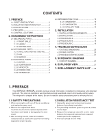
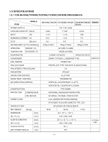
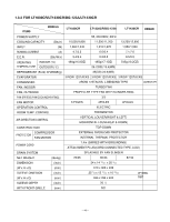
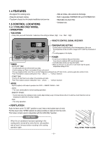
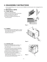
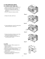
CONTENTS 1. PREFACE 1.1 SAFETY PRECAUTIONS 2 1.2 INSULATION RESISTANCE TEST 2 1.3 SPECIFICATIONS 3 1.4 FEATURES 5 1.5 CONTROL LOCATIONS 5 2. DISASSEMBLY INSTRUCTIONS 2.1 MECHANICAL PARTS 6 2.1.1 FRONT GRILLE 6 2.1.2 CABINET 6 2.1.3 CONTROL BOX 6 2.2 AIR HANDLING PARTS 7 2.2.1 ORIFICE, HEATER ASSY AND TURBO FAN .........7 2.2.2 FAN 7 2.2.3 SHROUD 8 2.3 ELECTRICAL PARTS 8 2.3.1 MOTOR 8 2.3.2 COMPRESSOR 8 2.3.3 CAPACITOR 8 2.3.4 POWER CORD 9 2.3.5 THERMISTOR 9 2.4 REFRIGERATION CYCLE 10 2.4.1 CONDENSER 10 2.4.2 EVAPORATOR 10 2.4.3 CAPILLARY TUBE 10 3. INSTALLATION 3.1 INSTALLATION REQUIREMENTS 13 3.2 INSTALLATION 14 3.3 PROCEDURE A 15 3.4 PROCEDURE B 16 3.5 PROCEDURE C 18 4. TROUBLESHOOTING GUIDE 4.1 OUTSIDE DIMENSIONS 20 4.2 PIPING SYSTEM 20 4.3 TROUBLESHOOTING GUIDE 21 5. SCHEMATIC DIAGRAM 5.1 CIRCUIT DIAGRAM 27 6. EXPLODED VIEW 27 7. REPLACEMENT PARTS LIST .......28 1. PREFACE This SERVICE MANUAL provides various service information, including the mechanical and electrical parts etc. This room air conditioner was manufactured and assembled under a strict quality control system. The refrigerant is charged at the factory. Be sure to read the safety precautions prior to servicing the unit. 1.1 SAFETY PRECAUTIONS 1. When servicing the unit, turn off the air conditioner and unplug the power cord. 2. Observe the original lead dress. If a short circuit is found, replace all parts which have been overheated or damaged by the short circuit. 3. After servicing the unit, make an insulation resistance test to protect the customer from being exposed to shock hazards. 1.2 INSULATION RESISTANCE TEST 1. Unplug the power cord and connect a jumper between 2 pins (black and white). 2. The grounding conductor (green or green & yellow) is to be open. 3. Measure the resistance value with an ohm meter between the jumpered lead and each exposed metallic part on the equipment. 4. The value should be over 1MΩ. -2-

  • 1
  • 2
  • 3
  • 4
  • 5
  • 6
  • 7
  • 8
  • 9
  • 10
  • 11
  • 12
  • 13
  • 14
  • 15
  • 16
  • 17
  • 18
  • 19
  • 20
  • 21
  • 22
  • 23
  • 24
  • 25
  • 26
  • 27
  • 28
  • 29
  • 30
  • 31
  • 32
  • 33
  • 34
  • 35
  • 36
  • 37
  • 38
  • 39

—2—
1. PREFACE
1.1 SAFETY PRECAUTIONS
...............................
2
1.2 INSULATION RESISTANCE TEST
.................
2
1.3 SPECIFICATIONS
..........................................
3
1.4 FEATURES
.....................................................
5
1.5 CONTROL LOCATIONS
.................................
5
2.
DISASSEMBLY INSTRUCTIONS
2.1 MECHANICAL PARTS
....................................
6
2.1.1 FRONT GRILLE
.....................................
6
2.1.2 CABINET
................................................
6
2.1.3 CONTROL BOX
.....................................
6
2.2 AIR HANDLING PARTS
..................................
7
2.2.1
ORIFICE, HEATER ASSY AND TURBO FAN
.........
7
2.2.2 FAN
........................................................
7
2.2.3 SHROUD
................................................
8
2.3 ELECTRICAL PARTS
.....................................
8
2.3.1 MOTOR
..................................................
8
2.3.2 COMPRESSOR
.....................................
8
2.3.3 CAPACITOR
..........................................
8
2.3.4 POWER CORD
....................................
..9
2.3.5 THERMISTOR
.....................................
..9
2.4 REFRIGERATION CYCLE
.................................
1
0
2.4.1 CONDENSER
......................................
1
0
2.4.2 EVAPORATOR
....................................
1
0
2.4.3 CAPILLARY TUBE
...............................
1
0
3.
INSTALLATION
3.1 INSTALLATION REQUIREMENTS
...............
1
3
3.2 INSTALLATION
.............................................
1
4
3.3 PROCEDURE A
............................................
1
5
3.4 PROCEDURE B
............................................
1
6
3.5 PROCEDURE C
............................................
1
8
4.
TROUBLESHOOTING GUIDE
4.1 OUTSIDE DIMENSIONS
...............................
2
0
4.2 PIPING SYSTEM
..........................................
2
0
4.3 TROUBLESHOOTING GUIDE
......................
2
1
5. SCHEMATIC DIAGRAM
5.1 CIRCUIT DIAGRAM
......................................
2
7
6. EXPLODED VIEW
..................................
2
7
7. REPLACEMENT PARTS LIST
.......
2
8
1. PREFACE
This
SERVICE MANUAL
provides various service information, including the mechanical and electrical
parts etc. This room air conditioner was manufactured and assembled under a strict quality control system.
The refrigerant is charged at the factory. Be sure to read the safety precautions prior to servicing the unit.
1.1 SAFETY PRECAUTIONS
1. When servicing the unit, turn off the air conditioner
and unplug the power cord.
2. Observe the original lead dress.
If a short circuit is found, replace all parts which
have been overheated or damaged by the short
circuit.
3. After servicing the unit, make an insulation
resistance test to protect the customer from being
exposed to shock hazards.
1.2
INSULATION RESISTANCE TEST
1. Unplug the power cord and connect a jumper
between 2 pins (black and white).
2. The grounding conductor (green or green & yellow)
is to be open.
3. Measure the resistance value with an ohm meter
between the jumpered lead and each exposed
metallic part on the equipment.
4. The value should be over 1M
.
CONTENTS