LG BG-101A Service Manual - Page 9
Power Cord, 3.5 Thermistor
 |
View all LG BG-101A manuals
Add to My Manuals
Save this manual to your list of manuals |
Page 9 highlights
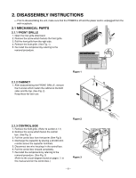
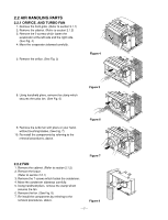
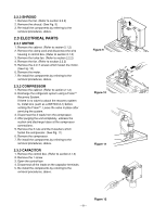
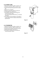
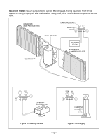
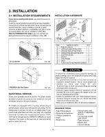
2.3.4 POWER CORD 1. Remove the control box. (Refer to section 2.1.3) 2. Unfold the control box. (Refer to section 2.3.3) 3. Disconnect the grounding screw from the Base pan. 4. Disconnect 2 receptacles. 5. Remove a screw which fastens the clip cord. 6. Pull the power cord. (See Fig. 13) 7. Re-install the components by referring to the removal procedure, above. (Use only one ground-marked hole, , for ground connection.) 8. If the supply cord of this appliance is damaged, it must be replaced with the factory-authorized and specified cord. Figure 13 2.3.5 THERMISTOR 1. Remove the control box. (Refer to section 2.1.3) 2. Unfold the control box. (Refer to section 2.3.3) 3. Disconnect all the leads of thermistor terminals. 4. Remove the thermistor. (See Fig. 14) 5. Re-install the components by referring to the removal procedures, above. ESnaevCregoryol Fan MODE Timer TIMER FF3F2H1MILGEOHDW TEMP 'F SPFEAEND POWER Figure 14 -9-
-
 1
1 -
2
-
3
-
 4
4 -
 5
5 -
 6
6 -
 7
7 -
 8
8 -
 9
9 -
 10
10 -
 11
11 -
 12
12 -
 13
13 -
 14
14 -
15
-
16
-
17
-
18
-
19
-
20
-
21
-
22
-
23
-
24
-
25
-
26
-
27
-
28
-
29
-
30
-
31
-
32
-
33
-
34
-
35
-
36
-
37
-
38
-
39
 |
 |
