LG DH65EL Service Manual
LG DH65EL Manual
 |
View all LG DH65EL manuals
Add to My Manuals
Save this manual to your list of manuals |
LG DH65EL manual content summary:
- LG DH65EL | Service Manual - Page 1
http://biz.LGservice.com Dehumidifier SERVICE MANUAL MODEL: DH30 DH40 DH50 DH50E DH50EL DH65EL DHR-3030 DHE-3031 DHR-4030 DHE-4031 DHR-5030 CAUTION - BEFORE SERVICING THE UNIT, READ THE SAFETY PRECAUTIONS IN THIS MANUAL. - ONLY FOR AUTHORIZED SERVICE. - LG DH65EL | Service Manual - Page 2
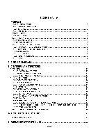
DEHUMIDIFIER 6 1.6.1 HOW DOES THE DEHUMIDIFIER WORK? 6 1.6.2 LOCATION FOR THE DEHUMIDIFIER 6 1.6.3 MICRO SWITCH 6 1.6.4 AUTO DEFROST 6 1.6.5 HUMIDITY CONTROLLER 7 1.6.6 DRYER 7 2. CIRCUIT DIAGRAM 8 3. DISASSEMBLY INSTRUCTIONS SYSTEM 18 4. TROUBLESHOOTING GUIDE 20 5. EXPLODED VIEWS - LG DH65EL | Service Manual - Page 3
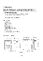
Service Manual provides various service information, including the mechanical and electrical parts. This dehumidifier was manufactured and assembled under the strict quality control procedures. The refrigerant is charged at the factory. Be sure to read the safety precaution prior to servicing /DH65EL - LG DH65EL | Service Manual - Page 4
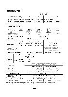
) 30 40 50 CONTROL PANEL MECHANICAL TYPE DH30, DHR-3030 DH40, DHR-4030 DH50, DHR-5030 ELECTRONIC TYPE DHE-3031 DHE-4031 DH50E, DH50EL 65 DH65EL 1.4 SPECIFICATIONS ITEMS MODELS CAPACITY (Pints/24hrs) DH30 DHR-3030 DHE-3031 30 DH40 DHR-4030 DHE-4031 40 DH50 DHR-5030 DH5OE DH5OEL* 50 - LG DH65EL | Service Manual - Page 5
to a higher setting. MAX is the highest setting. • When excess moisture and dampness odors are gone, adjust the control to a lower setting. Use the dehumidifier as long as excess moisture is present. Fan Speed • The fan control adjusts the fan speed. Set the fan control to HIGH for maximum moisture - LG DH65EL | Service Manual - Page 6
designed to be operated at temperatures above 65°F(18°C) in normal conditions. If the dehumidifier is operated in low temperature conditions frost can form in the evaporator coil and the unit operation feature in the DH50EL and DH65EL models will continuously cycle up to a temperature of 43°F(6°C). - LG DH65EL | Service Manual - Page 7
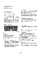
Humidity Control toward Off. The relative humidity range is from 20% to 80%. (See Figure 6) Turn the Humidity Control to Off to stop the unit manually. 1.6.5.2 Electronic Type The humidity control can be set 'on' or 35%-70% RH(Relative Humidity) for normal operation. (See Figure 7) If you need drier - LG DH65EL | Service Manual - Page 8
) ASSEMBLY, MAIN PART NO. DH30/DHR-3030 6411A20001Y 6600FX5001E 4681A20040E 6748C-0003D 2521C-A8626 6750C-0009E 6871A20169B 6877A30013G 6601A30001B 6600A30003C 6871A30032B Q'TY REPER SET MARKS 1 S 1 S 1 S 1 S 1 S 1 S 1 S 1 S 1 S 1 S 1 S S: SERVICE PARTS A: ALTERNATE PARTS -8- N: NOT - LG DH65EL | Service Manual - Page 9
, MICRO 9 PWB(PCB) ASSEMBLY, MAIN PART NO. DHE-3031 6411A20001Y 4681A20040E 6748C-0003D 2521C-A8626 6750C-0009E 6871A20279A 6877A30013H 6600A30003C 6871A20162K Q'TY REPER SET MARKS 1 S 1 S 1 S 1 S 1 S 1 S 1 S 1 S 1 S S: SERVICE PARTS A: ALTERNATE PARTS N: NOT - LG DH65EL | Service Manual - Page 10
0CZZA20003D 0CZZA20001R 5416A90009A 2520UCDA003 6751A20001F 6750U-L058A 6871A20169B 6877A30013G 6877A30013H 6601A30001B 6600A30003C 6871A30032A 6871A3032B Q'TY REPER SET MARKS 1 S 1 S 1 S 1 S 1 S 1 S 1 S 1 S 1 S 1 S 1 S x S: SERVICE PARTS A: ALTERNATE PARTS N: NOT - LG DH65EL | Service Manual - Page 11
4681A20040E 0CZZA20003D 0CZZA20001R 5416A90009A 2520UCDA003 6751A20001F 6750U-L058A 6871A20279A 6877A30013H 6600A30003C 6871A20162L 6871A20162K S: SERVICE PARTS A: ALTERNATE PARTS N: NOT SERVICE PARTS Q'TY REPER SET MARKS 1 S 1 S 1 S 1 S 1 S 1 S 1 S 1 S 1 S - LG DH65EL | Service Manual - Page 12
COIL ASSEMBLY, SOLENOID PART NO. DH5OEL DH65EL 6411A20001Z 4681A20040E 0CZZA20001R 6120AR2359V 2520UCDA003 2520UCDA004 6750U-L058A 6750U-L048A 6871A20279A 6877A30013H 6600A30003C 6871A20162E 6421A20003E S: SERVICE PARTS A: ALTERNATE PARTS N: NOT SERVICE PARTS Q'TY REPER SET MARKS - LG DH65EL | Service Manual - Page 13
3. DISASSEMBLY INSTRUCTIONS 3.1 MECHANICAL PARTS 3.1.1 BUCKET AND AIR FILTER 1. Turn the Humidity Control off(Mechanical type) or press the power button off. (Electronic type) ,g- 2. Disconnect the power supply. 3. - LG DH65EL | Service Manual - Page 14
3.2 CONTROL PARTS 3.2.1 POWER CORD ASSEMBLY 1. After opening the control box, remove the screw that holds the ground wire. (See Figure 15) 2. Disconnect the remaining leads of the power cord from the PWB(PCB) ASSEMBLY, MAIN, then remove it from the control box. 3.2.2 SENSOR ASSEMBLY 1. Disconnect - LG DH65EL | Service Manual - Page 15
PWB(PCB) ASSEMBLY, DISPLAY after turning over both hooks of the display cover. 3.2.6.2 CONTROL PANEL - Electronic Type (DHE-3031/DHE-4031/DH50E/DH50EL/DH65EL) 1. Disconnect the housing of the PWB(PCB) ASSEMBLY, DISPLAY from PWB(PCB) ASSEMBLY, MAIN (3.1.3). 2. Remove 5 screws that secure the PWB(PCB - LG DH65EL | Service Manual - Page 16
3.2.8 HOUSING ASSEMBLY, FAN AND MOTOR 1. Remove 4 screws that fasten the housing assembly to the heat exchanger and drain pan. Lift the housing assembly upward after unhooking 2 hooks on the housing. (See Figure 22) 2. Remove the screw that secures the housing and orifice. Separate the orifice from - LG DH65EL | Service Manual - Page 17
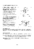
3.3 REFRIGERATING CYCLE 3.3.1 CONDENSER, EVAPORATOR AND CAPILLARY TUBE 1. Remove the insulation on the Heater/Evaporator (H/E) assembly 2. Pierce the pinch-off tube to discharge the refrigerant, using a refrigerant recovery system. 3. After discharging the refrigerant completely, remove 2 screws - LG DH65EL | Service Manual - Page 18
discharge the refrigerant system by using a refrigerant recovery system. 2. After discharging the unit completely, remove the desired component, and unbraze the pinch-off tubes. 3. Solder service valves into the pinch-off tube ports, leaving the valves open. 4. Solder the pinch-off tubes with - LG DH65EL | Service Manual - Page 19
equipment. pinch-off tool capable of making a vapor-proof seal, leak detector, tubing cutter, hand tools to remove components, service valve. EVAPORATOR ASSEMBLY (LOW PRESSURE SIDE) CONDENSER ASSEMBLY (HIGH PRESSURE SIDE) COMPOUND GAUGE 1 MANIFOLD GAUGE A B EVAPORATOR ASSEMBLY (LOW PRESSURE - LG DH65EL | Service Manual - Page 20
4. TROUBLESHOOTING GUIDE CONDITION 1. Dehumidifier does not start. (Both compressor and fan motor do Does not defrost control. 4. Insufficient dehumidification Capacitor (Discharge capacitor before servicing.) Compressor Overload protector (OLP) Defrost control is defective. Low relative humidity - LG DH65EL | Service Manual - Page 21
off. Check micro switch and float. Check line voltage. It must be between 103.5V and 126.5V volts. If intermittent, provide new supply. Move dehumidifier for free and unobstructed air flow. Clean dust or dirt on the Heat Exchange. If not running, determine the cause. Replace if required. Check PTC - LG DH65EL | Service Manual - Page 22
• MODEL: DH40/DHR-4030 0 C Z 64110 4995'0 5211 68714 336610 35901 036690 • Q 21948() 346811 54210 0.5416-0 49600 1 05403-0 56750 52111 Q.-a83 01 048381)T 6871 • 3551 149410 149400 66003 6600 162615 550140 135500 0 -3000 436500 O 14, 66011 •••c•k?`,"' Cl309 144410 131110 - LG DH65EL | Service Manual - Page 23
• MODEL: DH4O/DHR-4030 LOCATION NO. DESCRIPTION 130411 BASE ASSEMBLY, WELD (SINGLE) 130910 CABINET ASSEMBLY 131110 CASE ASSEMBLY 330870 DRAIN PAN ASSEMBLY 148380 TANK, ASSEMBLY BUCKET 149410 KNOB ASSEMBLY 152302 FILTER(MECH), AIR 162615 SENSOR ASSEMBLY WOCZZ CAPACITOR 249950 CONTROL BOX - LG DH65EL | Service Manual - Page 24
LG Electronics Inc. P/No : 3828A20090H October, 2004 Printed in Korea
-
 1
1 -
 2
2 -
 3
3 -
 4
4 -
 5
5 -
 6
6 -
 7
7 -
8
-
9
-
10
-
11
-
12
-
13
-
14
-
15
-
16
-
17
-
18
-
19
-
20
-
21
-
22
-
23
-
24
 |
 |
Dehumidifier
SERVICE
MANUAL
MODEL:
DH30
DH40
DH50
DH50E
DH50EL
DH65EL
DHR-3030
DHE-3031
DHR-4030
DHE-4031
DHR-5030
CAUTION
-
BEFORE
SERVICING
THE
UNIT,
READ
THE
SAFETY
PRECAUTIONS
IN
THIS
MANUAL.
-
ONLY
FOR
AUTHORIZED
SERVICE.