LG DH65EL Service Manual - Page 15
Assembly, Solenoid, Dh5oel/dh65el, Control, Panel
 |
View all LG DH65EL manuals
Add to My Manuals
Save this manual to your list of manuals |
Page 15 highlights
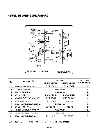
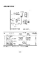
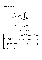
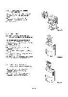
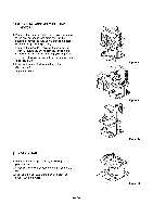
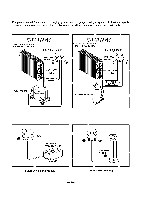
3.2.6 COIL ASSEMBLY, SOLENOID (DH5OEL/DH65EL) 1. Disconnect the housing of the COIL ASSEMBLY, SOLENOID from the PCB(PWB) ASSEMBLY, MAIN. 2. Remove the screw that fastens the COIL ASSEMBLY, SOLENOID. (See Figure 19) 3. Pull it out upwards. 3.2.7 CONTROL PANEL 3.2.6.1 CONTROL PANEL - Mechanical Type (DH30/DHR-3030/DH40/DHR-4030/DH50/DHR-5030) 1. Disconnect housing and all leads of the rocker switch, SWITCH ASSEMBLY, ROTARY and PWB(PCB) ASSEMBLY, DISPLAY from PWB(PCB) ASSEMBLY, MAIN (3.1.3) 2. Pull out the knob assembly. 3. Remove the nut which fastens the SWITCH ASSEMBLY, ROTARY. 4. Remove the knob of the rotary switch by pulling it upward. 5. Pull out the rocker switch by pushing the hooks on the both sides of rocker switch. 6. Pull out the PWB(PCB) ASSEMBLY, DISPLAY after turning over both hooks of the display cover. 3.2.6.2 CONTROL PANEL - Electronic Type (DHE-3031/DHE-4031/DH50E/DH50EL/DH65EL) 1. Disconnect the housing of the PWB(PCB) ASSEMBLY, DISPLAY from PWB(PCB) ASSEMBLY, MAIN (3.1.3). 2. Remove 5 screws that secure the PWB(PCB) ASSEMBLY, DISPLAY to the display cover. -15- k,,,i..r.- k• 1 irk •i*t Fr% ir k` I' 4g, Figure 19 Figure 20 Figure 21
-
 1
1 -
2
-
3
-
4
-
5
-
6
-
7
-
8
-
9
-
 10
10 -
 11
11 -
 12
12 -
 13
13 -
 14
14 -
 15
15 -
 16
16 -
 17
17 -
 18
18 -
 19
19 -
 20
20 -
21
-
22
-
23
-
24
 |
 |
