LG DH65EL Service Manual - Page 17
Refrigerating, Cycle
 |
View all LG DH65EL manuals
Add to My Manuals
Save this manual to your list of manuals |
Page 17 highlights
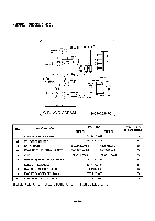
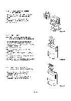
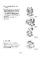
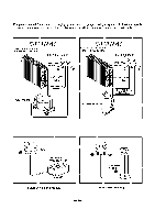
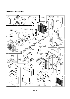
3.3 REFRIGERATING CYCLE 3.3.1 CONDENSER, EVAPORATOR AND CAPILLARY TUBE 1. Remove the insulation on the Heater/Evaporator (H/E) assembly 2. Pierce the pinch-off tube to discharge the refrigerant, using a refrigerant recovery system. 3. After discharging the refrigerant completely, remove 2 screws between the housing assembly and the H/E. (See Figure 26) 4. Lift the H/E and open the H/E around 45 degree counterclockwise carefully. 5. Unbraze each of interconnecting tubes of the evaporator and condenser carefully. 6. Remove the H/E assembly from the orifice. (See Figure 27) 7. Unbraze the capillary tube at the connections of the condenser and evaporator. (See Figure 28) 8. Remove 4 screws between the condenser and evaporator. (See Figure 28) 3.3.2 PTC OR OVERLOAD PROTECTOR (OLP) FOR RECIPROCATING COMPRESSOR (DH30/DHR-3030/DHE-3031) 1. Discharge the refrigerant by using a refrigerant Recovery System. 2. After purging the unit completely, unbraze the suction and discharge tubes at the compressor connections. 3. Remove the screw or nut which fastens the terminal cover 4. Disconnect the lead wire from the overload protector or PTC assembly. 5. Remove the overload protector(OLP) or PTC assembly. (See Figure 29) 3.3.3 ROTARY COMPRESSOR 1. Discharge the refrigerant by using a refrigerant Recovery System. 2. After purging the unit completely, unbraze the suction and discharge tubes at the compressor connections. 3. Remove the nuts and washers which fasten the compressor. (See Figure 30) 4. Remove the compressor. (See Figure 30) I 40'N, 4O' Figure 26 41t.4 .*; ,t1 Figure 27 Figure 28 Using Recipro Compressor model Figure 29 Using Rotary Compressor models -17- Figure 30
-
 1
1 -
2
-
3
-
4
-
5
-
6
-
7
-
8
-
9
-
10
-
11
-
 12
12 -
 13
13 -
 14
14 -
 15
15 -
 16
16 -
 17
17 -
 18
18 -
 19
19 -
 20
20 -
 21
21 -
 22
22 -
23
-
24
 |
 |
