LG DH65EL Service Manual - Page 13
Disassembly, Instructions
 |
View all LG DH65EL manuals
Add to My Manuals
Save this manual to your list of manuals |
Page 13 highlights
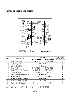
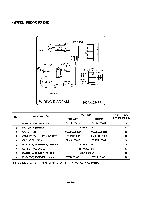
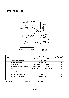
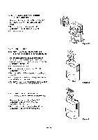
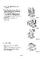
3. DISASSEMBLY INSTRUCTIONS 3.1 MECHANICAL PARTS 3.1.1 BUCKET AND AIR FILTER 1. Turn the Humidity Control off(Mechanical type) or press the power button off. (Electronic type) ,g- 2. Disconnect the power supply. 3. Remove the bucket. (See Figure 9) 4. Pressing the hooks, pull out the air filter. (See Figure 10) Figure 9 Figure 10 3.1.2 FRONT CASE AND TOP COVER 1. Remove 4 screws which fasten the front case. 2. Pull the front case from the bottom and lift up. (See Figure 11) 3. Remove 2 screws that secure the top cover. 4. Remove the top cover. (See Figure 12) 3.1.3. CABINET AND CONTROL BOX (Upper) 1. Remove the bucket, air filter and top cover according to the procedure above. 2. Remove the screw from the top of the control box (upper), and pull out the control box. (See Figure 13) 3. Disconnect all wires from control box(lower) and remove front case completely. 4. Remove 7 screws from the back and sides. 5. Lift up the cabinet a little from the base pan and separate it by pulling out backward. (See Figure 14) I0 • Figure 11 Figure 12 00*- O Figure 13 Figure 14 -13-
-
 1
1 -
2
-
3
-
4
-
5
-
6
-
7
-
 8
8 -
 9
9 -
 10
10 -
 11
11 -
 12
12 -
 13
13 -
 14
14 -
 15
15 -
 16
16 -
 17
17 -
 18
18 -
19
-
20
-
21
-
22
-
23
-
24
 |
 |
