LG DLG5932W Service Manual
LG DLG5932W Manual
 |
View all LG DLG5932W manuals
Add to My Manuals
Save this manual to your list of manuals |
LG DLG5932W manual content summary:
- LG DLG5932W | Service Manual - Page 1
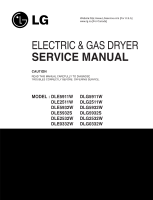
www.LGservice.com [For U.S.A] www.lg.ca [For Canada] ELECTRIC & GAS DRYER SERVICE MANUAL CAUTION READ THIS MANUAL CAREFULLY TO DIAGNOSE TROUBLES CORRECTLY BEFORE OFFERING SERVICE. MODEL : DLE5911W DLE2511W DLE5932W DLE5932S DLE2532W DLE0332W DLG5911W DLG2511W DLG5932W DLG5932S DLG2532W DLG0332W - LG DLG5932W | Service Manual - Page 2
MAR. 2003 PRINTED IN KOREA P/No.:3828EL3001B - LG DLG5932W | Service Manual - Page 3
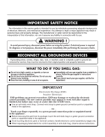
light a match, or cigarette, or turn on any gas or electrical appliance. Do not touch any electrical switches. Do not use any phone in your building. Clear the room, building or area of all occupants. Immediately call your gas supplier from a neighbor's phone. Follow the gas supplier's instructions - LG DLG5932W | Service Manual - Page 4
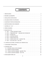
6 HEATER SWITCH TEST - ELECTRIC TYPE 22 9-7. TEST 7 GAS VALVE TEST - GAS TYPE 23 10. CHANGE GAS SETTING (NATURAL GAS, PROPANE GAS 24 11. DISASSEMBLY INSTRUCTIONS 26 12. EXPLODED VIEW ...32 12-1. CONTROL PANEL & PLATE ASSEMBLY 32 12-2. CABINET & DOOR ASSEMBLY 33 12-3-1. DRUM & MOTOR ASSEMBLY - LG DLG5932W | Service Manual - Page 5
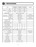
DLG5932S DLG2532W 120V AC 240V ( ELECTRIC TYPE) AC 120V GAS VALVE 13W (110mA) X 2 AC 120V ( GAS TYPE) CONTROL TYPE Electronic DRUM CAPACITY 7.3 cu.ft. Weight (lbs): Net Door Adopted Drum Stainless Steel Dryer Rack Equipped Child lock Equipped Interior Light Equipped Product - LG DLG5932W | Service Manual - Page 6
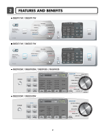
2 FEATURES AND BENEFITS DLE5911W / DLG5911W DLE2511W / DLG2511W DLE5932W / DLG5932W / DLE5932S / DLG5932S DLE2532W / DLG2532W 5 - LG DLG5932W | Service Manual - Page 7
wires to outer terminal block screws. Tighten screws. 6. Tighten strain relief screws. 7. Insert tab of terminal block cover into slot of dryer rear panel Secure cover with hold-down screw. 1. External ground connector - Dotted line shows position of NEUTRAL ground wire before being moved to center - LG DLG5932W | Service Manual - Page 8
wires to outer terminal block screws. Tighten screws. 4. Tighten strain relief screws. 5. Insert tab of terminal block cover into slot of dryer rear panel. Secure cover with hold-down screw. 6. Connect a separate copper ground wire from the external ground connector screw to an adequate ground - LG DLG5932W | Service Manual - Page 9
shipping cap from the gas connection at the rear of the dryer. Make sure you do not damage the pipe thread when removing the cap. 3. Connect to gas supply pipe using a new flexible stainless steel connector. 4. Tighten all connections securely. Turn on gas and check all pipe connections (internal - LG DLG5932W | Service Manual - Page 10
) (47±5°C) 3Hr Air dry - - 30min Saturation No heater N/A N/A Load Motor Heater Off Time: 6min On Time: 10sec Temperature Control for each cycle * Sense dry : "Dry Level" is set by users. ** Manual dry : "Temperature control" is set by users. Default settings can be adjusted by users. 9 - LG DLG5932W | Service Manual - Page 11
sufficiently. Component 1. Thermal cut off • Check Top Marking : N130 2. Hi limit Thermostat (Auto reset) 3. Outlet Thermostat ( Auto reset) • Check Top Marking : N85 4. Lamp holder Test Procedure Check result Remark Measure resistance of terminal If thermal fuse is open must • Heater case- to - LG DLG5932W | Service Manual - Page 12
) - 2 Terminal : 1 (COM) - 3 Terminal : 2 - 3 Check result Resistance value : 10Ω Resistance value : 10Ω Resistance value : 20Ω Gas type Resistance value : > 1.5kg ~ Resistance value : > 1.5~2.5kg 11. Igniter valve 2 Measure resistance of terminal to terminal Resistance value : 100~800Ω • Gas - LG DLG5932W | Service Manual - Page 13
Auto reset) • Check Top Marking : N95 13. Outlet Thermostat (Manual reset) • Check Top Marking : N100 Test Procedure Measure resistance of terminal to terminal Open at 203 ± 7°F (95 ± 5°C) Close at 158 ± 9°F (70 ± 5°C) Check result Resistance value ∞ Continuity < 1Ω Remark • Gas type • Gas funnel - LG DLG5932W | Service Manual - Page 14
6 MOTOR DIAGRAM AND SCHEMATIC NOTE When checking Component, be sure to turn Power off, then do voltage discharge sufficiently. Contact On / Off by Centrifugal Switch STOP MODE (When Motor does not operate) RUN MODE (Motor operates) Centrifugal switch Centrifugal switch (Pull Drive forward) 13 - LG DLG5932W | Service Manual - Page 15
7 CONTROL LAY - OUT PWB ASSEMBLY DISPLAY LAY-OUT MODEL DISPLAY AS DIAGNOSTIC TEST MODEL DLE5932W/S DLG5932W DLE5911W DLG5911W OP 1 X X X X OPTION PART OP 2 OP 3 OP 4 OP 5 X X X X X O X X O X X X O O X X LED OP 6 DISPLAY P/No X 18:20 6871EC2025F X 19:20 6871EC2025G X 18: - LG DLG5932W | Service Manual - Page 16
8 WIRING DIAGRAM ELECTRIC DRYER WIRING DIAGAM GAS DRYER WIRING DIAGAM 15 - LG DLG5932W | Service Manual - Page 17
be used for Factory test /Service test. Do not use this DIAGNOSTIC TEST other than specified. 2. Activating the Heater manually with the Door open may trip the Thermostat attached to the Heater, therefore do not activate it manually. (Do not press the door switch to operate the heater while the - LG DLG5932W | Service Manual - Page 18
avoid an electric shock. Trouble Symptom No power was applied to Controller. (LED, Display off) Measurement Condition With Dryer Power On; Connector linked to Controller. Check the outlet, is the voltage 110V ~ 125V AC? YES NO • Check the fuse or circuit breaker. Check if the voltage measured - LG DLG5932W | Service Manual - Page 19
When discharging, contact the metal plug of Power cord with the Ground.) Trouble Symptom During Diagnostic Test, tE1 and tE2 Error occur. During operation, Heater off, measure the resistance. Take 6pin Connector from the Controller. Check if resistance is in the range of Table 1 when measuring - LG DLG5932W | Service Manual - Page 20
Control. (Relay check) • Check Controller connector. • Replace Outlet • Thermostat. (Refer to 'Component') • Check Idler Assembly. • Drum Belt cuts off • Drum Belt takes off from • Motor Pulley. • Replace Idler Switch. • Check Motor.(Refer to 'Motor Diagram & Check') • Check if Control Connector - LG DLG5932W | Service Manual - Page 21
Trouble Symptom Degree of dryness does not match with Dry Level. Measurement Condition Turn the Dryer's Power Off, then measure resistance. Take 6pin Connector from the Controller wire) and Pin (ORANGE wire)? YES • Replace Control and Check. Normal Condition Table 2. IMC Ratio and Display Value - LG DLG5932W | Service Manual - Page 22
Drum motor will not operate. Display will flash at 0.5 second intervals.) Measurement Condition After turning Dryer Power Off, measure resistance. Measure while Door is closed. Check from Controller. NO • Door switch Check (Refer to Component testing.) Measure while Door is closed. Check if - LG DLG5932W | Service Manual - Page 23
Test 6 Heater switch test - Electric Type Caution Before measuring resistance, be sure to turn Power off, and do voltage discharge. (When discharging, contact the metal plug of Power cord with earth line.) Trouble Symptom While operating, Heating will not work. Drying time takes longer. - LG DLG5932W | Service Manual - Page 24
electric shock. Trouble Symptom While operating, Heating will not work. Drying time takes longer. Measurement Condition With dryer power on Valve 1 Igniter Valve 2 Power On & Start (Normal Cycle) NO When measuring Valve 1 voltage, More than AC 90V? YES NO • Check thermostat Hi limit Safety - LG DLG5932W | Service Manual - Page 25
is set. Propane Gas Orifice is on sale as a Service Part to authorized servicers only. STEP 1 : VALVE SETTING Full open "Change screw" STEP 2 : ORIFICE CHANGE Orifice Close "Change screw" Remove 2 screws. Disassemble the pipe assembly. Replace Natural Gas orifice with Propane Gas orifice. Gas type - LG DLG5932W | Service Manual - Page 26
KEY PUSH "VALVE 1" ON IGNITE ON IGNITE TEMPERATURE ABOUT 370"F YES FRAME DETECT OPEN IGNITE OFF "VALVE 2" ON GAS IGNITION YES DRYING NO NO FRAME DETECT CLOSE "VALVE 2" OFF GAS IGNITION START VALVE 1 IGNITER FRAME DETECT VALVE 2 ON ON CLOSE OFF OFF OPEN ON GAS IGNITION GAS VALVE STRUCTURE 25 - LG DLG5932W | Service Manual - Page 27
11 DISASSEMBLY INSTRUCTIONS Disassemble and repair the unit only after pulling out power plug from the outlet. 1. Remove 3 screws on the rear Panel. 2. Pull the control panel forward. 3. Open the cover protect. 4. Disconnect connectors. 5. Remove 5 screws. 6. Disassemble the controller assembly. 26 - LG DLG5932W | Service Manual - Page 28
7cm 7cm 1. Push backward using an opener and lift the top plate. 1. Open the top plate. 2. Open the door, Remove 2 screws. 3. Remove 2 screws form upper side. 4. Pull the Cover Cabinet. 5. Disconnect the door switch connector. 27 - LG DLG5932W | Service Manual - Page 29
sensor connector. 4. Remove 4 screws. 5. Disassemble the Tub Drum [Front]. -1 1. Open the top plate. -1 2. Remove the Cover Cabinet and Tub drum [front]. -2 3. Disengage belt from motor and idler pulleys. 4. Carefully remove Drum out through front of dryer. 1. Open the door. 2. Remove the - LG DLG5932W | Service Manual - Page 30
4" elbow with 4" duct. Wrap duct tape around joint. DUCT TAPE 5. Insert duct assembly, elbow first, through the side opening and connect the elbow to the dryer internal duct. 29 - LG DLG5932W | Service Manual - Page 31
1. Remove the filter. 2. Remove 3 screws. 3. Pull the grill. 4. Disconnect electro sensor. 1. Open the top plate. 2. Remove the Cover Cabinet and Tub Drum [Front]. 3. Remove the Drum assembly. 4. Remove 2 screws and cover(Air guide). 5. Remove the bolt and washer. 6. Pull the fan. 7. Disconnect the - LG DLG5932W | Service Manual - Page 32
. 2. Remove the Cover Cabinet. 3. Remove filter and 2 screws. 4. Pull the air duct towards the front. 1. Open the top plate. 2. Remove the Cover Cabinet and Tub Drum [Front]. 3. Remove the Drum assembly and Tub Drum [Rear]. 4. Disconnect Air duct from the Tub Drum [Front]. 5. Remove the roller from - LG DLG5932W | Service Manual - Page 33
12 EXPLODED VIEW 12-1. Control Panel & Plate Assembly A120 A130 A150 A140 A110 A600 A210 A570 A215 A211 32 - LG DLG5932W | Service Manual - Page 34
12-2. Cabinet & Door Assembly A700 A800 A330 A340 A320 A300 A305 A310 A535 A400 A520 A540 A212 A500 A510 A430 A450 A410 A460 A420 33 - LG DLG5932W | Service Manual - Page 35
12-3-1. Drum & Motor Assembly : Electric Type F200 K400 K120 K140 K100 K130 K222 K221 K210 K240 K230 K350 F130 F110 F120 K250 K251 K330 K320 K340 K250 K251 K360 K550 K560 K310 K620 K610 F140 K515 K510 K540 K520 K640 K600 K530 K650 K651 34 - LG DLG5932W | Service Manual - Page 36
12-3-2. Drum & Motor Assembly : Gas type F200 K400 K120 K100 K140 K130 K222 K221 K210 K230 K350 K250 K251 K330 K320 K340 K250 K251 K360 K510 K540 K520 K640 K530 M150 M240 M220 K650 M141 K600 K651 M190 M180 M230 M250 M210 M171 : Propane Gas orifice M170 : Natural Gas orifice 35 - LG DLG5932W | Service Manual - Page 37
13 REPLACEMENT PARTS LIST 36 - LG DLG5932W | Service Manual - Page 38
37
-
 1
1 -
 2
2 -
 3
3 -
 4
4 -
 5
5 -
 6
6 -
 7
7 -
8
-
9
-
10
-
11
-
12
-
13
-
14
-
15
-
16
-
17
-
18
-
19
-
20
-
21
-
22
-
23
-
24
-
25
-
26
-
27
-
28
-
29
-
30
-
31
-
32
-
33
-
34
-
35
-
36
-
37
-
38
 |
 |
Website:http://www.LGservice.com [For U.S.A]
www.lg.ca [For Canada]
ELECTRIC & GAS DRYER
SERVICE MANUAL
CAUTION
READ THIS MANUAL CAREFULLY TO DIAGNOSE
TROUBLES CORRECTLY BEFORE
OFFERING SERVICE.
MODEL : DLE5911W
DLE2511W
DLE5932W
DLE5932S
DLE2532W
DLE0332W
DLG5911W
DLG2511W
DLG5932W
DLG5932S
DLG2532W
DLG0332W