LG HBLG6000R Service Manual - Page 6
Disassembly Instructions - manual
 |
View all LG HBLG6000R manuals
Add to My Manuals
Save this manual to your list of manuals |
Page 6 highlights
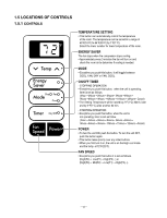
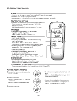
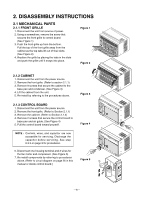
2. DISASSEMBLY INSTRUCTIONS 2.1 MECHANICAL PARTS 2.1.1 FRONT GRILLE 1. Disconnect the unit from source of power. 2. Using a screwdriver, remove the screw that secures the front grille to control board. (See Figure 1) 3. Push the front grille up from the bottom. Pull the top of the front grille away from the cabinet as the top tabs lift out of their slots. (See Figure 2) 4. Replace the grille by placing the tabs in the slots and push the grille until it snaps into place. Figure 1 Figure 2 2.1.2 CABINET 1. Disconnect the unit from the power source. 2. Remove the front grille. (Refer to section 2.1.1) 3. Remove 9 screws that secure the cabinet to the base pan and condenser. (See Figure 3) 4. Lift the cabinet from the unit. 5. Re-install by referring to the procedures above. 2.1.3 CONTROL BOARD 1. Disconnect the unit from the power source. 2. Remove the front grille. (Refer to Section 2.1.1) 3. Remove the cabinet. (Refer to Section 2.1.2) 4. Remove 2 screws that secure the control board to base pan and air guide. (See Figure 4) 5. Pull the control board toward yourself. NOTE : Controls, wires, and capacitor are now accessible for servicing. Discharge the capacitor before servicing. See step 2.3.3 on page 9 for procedures. 6. Disconnect one housing terminal and 3 wires for the fan motor and compressor. (See Figure 5) 7. Re-install components by referring to procedures above. (Refer to circuit diagram on page 26 in this manual or inside control board.) Figure 3 Figure 4 Figure 5 -6-
-
 1
1 -
 2
2 -
 3
3 -
 4
4 -
 5
5 -
 6
6 -
 7
7 -
 8
8 -
 9
9 -
 10
10 -
 11
11 -
 12
12 -
13
-
14
-
15
-
16
-
17
-
18
-
19
-
20
-
21
-
22
-
23
-
24
-
25
-
26
-
27
-
28
-
29
-
30
-
31
-
32
-
33
-
34
 |
 |
