LG HBLG6000R Service Manual - Page 9
Compressor, 3.3 Capacitor, 3.4 Thermistor, 3.5 Control Panel
 |
View all LG HBLG6000R manuals
Add to My Manuals
Save this manual to your list of manuals |
Page 9 highlights
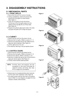
2.3.2 COMPRESSOR 1. Remove the front grille and cabinet. (Refer to Section 2.1.2) 2. Discharge the refrigerant by using a refrigerant recovery system. 3. Remove the overload protector. (Refer to Section 2.3.1) 4. After discharging the unit completely, unbrace the suction and discharge pipes at the compressor connections. 5. Remove 3 nuts which fasten the compressor. 6. Remove the compressor. 7. Re-install by referring to the removal procedure above. (See Figure 14) Figure 14 2.3.3 CAPACITOR 1. Remove the cabinet. (Refer to Section 2.1.2) 2. Remove the control board. (Refer to Section 2.1.3) 3. Discharge the capacitor by placing a 20 KΩ resistor across the capacitor terminals. 4. Pull the capacitor upward. 5. Remove all the leads of capacitor terminals. 6. Re-install the components by referring to the removal procedure above. (See Figure 15) Figure 15 2.3.4 THERMISTOR 1. Remove the cabinet. (Refer to Section 2.1.2) 2. Remove the control board. (Refer to Section 2.1.3) 3. Disconnect the thermistor terminals from main P.W.B assembly. 4. Remove the thermistor. 5. Re-install the components by referring to the removal procedure above. (See Figure 16) 2.3.5 CONTROL PANEL 1. Remove the cabinet. (Refer to Section 2.1.2) 2. Remove the control board. (Refer to Section 2.1.3) 3. Pull the control panel forward and pull out it. 4. Remove 2 lead wire terminals. 5. Re-install the components by referring to the removal procedure above. (See Figure 17) Figure 16 Figure 17 -9-
-
 1
1 -
2
-
3
-
 4
4 -
 5
5 -
 6
6 -
 7
7 -
 8
8 -
 9
9 -
 10
10 -
 11
11 -
 12
12 -
 13
13 -
 14
14 -
15
-
16
-
17
-
18
-
19
-
20
-
21
-
22
-
23
-
24
-
25
-
26
-
27
-
28
-
29
-
30
-
31
-
32
-
33
-
34
 |
 |
