LG RCS10MPA Service Manual - Page 24
H. High Voltage Transformer, Removal, I. Fan Motor Assembly Removal, J. High Voltage Capacitor And,
 |
View all LG RCS10MPA manuals
Add to My Manuals
Save this manual to your list of manuals |
Page 24 highlights
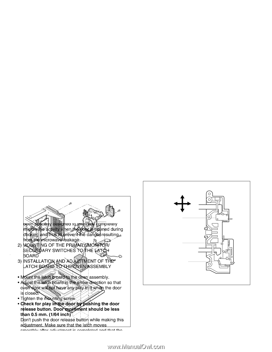
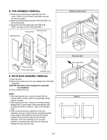
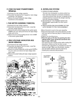
H. HIGH VOLTAGE TRANSFORMER REMOVAL H. H1)IDGisHchaVrgOeLthTeAhGighEvoTltRagAe NcaSpaFcOitoRr. MER R2)EDMiscOonVnAecLt the leadwire from magnetron, high voltage 1) Discthraanrgseforthmeerh,igahndvocaltpaagceitcoar.pacitor. 2) D3is)cRoenmneocvtetthheelsecardewwirheofldroinmg mthaeghnigehtrovnol,tahgigeh voltage trantsrfaonrsmfoerrm, aenr dtoctahpeabcaitsoerp. late. 3) Remove the screw holding the high voltage trIa. nFsAfoNrmeMr OtoTthOeRboAttoSmSpElaMteB. LY REMOVAL 1) Discharge the high voltage capacitor. I. B2L) DOisWcoEnnRecMt thOe TleOadRwirAe fSroSmEfaMn BmoLtoYr, RnoEisMe fiOlteVr AL and high voltage capacitor. 1) D3is)cRoenmneocvtetthheeltewaodwscirreewfrsomhobldlionwgethr emtohteors.uction guide 2) RemAoSvSe'Ythetottwhoe socvreenwcsahviotyldainngd trheembolvoewtehremhiogthorvoltage to thdeiobdoettoemartphlasctere. w. 4) Remove the two screws holding the fan motor ASS'Y J. HIGtoHtheVsOucLtioTnAgGuidEe ACSAS'PY.ACITOR AND DIODE REMOVAL 1) DJis.cHhaIrGgeHthVeOhiLghTAvoGltaEgeCcAapPaAcitCorI.TOR AND 2) DiscoDnInOecDt EtheRleEaMdwOirVe AfroLm high voltage capacitor. 3) R1e)mDoisvcehtahregescthrewhihgohldvoinltgagtheecahpigahcivtoorl.tage diode e2a)rtDhiscorenwne. ct the leadwire from fan motor, noise filter 4) Remaonvdehtihgeh svcorlteawgehocaldpinacgittohre. high voltage capacitor b3r)acRkeemt.ove the screw holding the suction guide ASS'Y to the oven cavity and remove the high voltage diode earth screw. 4) Remove the screw holding the high voltage capacitor bracket. Fan Motor ASS'Y K. INTERLOCK SYSTEM 1) INTERLOCK MECHANISM K. ITNhTe EdoRoLr lOocCk mKeSchYanSisTmEiMs a device which has 1) INbTeEenRLspOeCciKalMly EdeCsHigAnNedIStMo eliminate completely Tmheicrdoowoarvloecakcmtiveitcyhwahneisnmthies adodoervisicoepwehniecdhdhuarsing bceoeonksinpgeacinadllythduesstiognperedvteontetlihmeindaatnegecor mrepsulelttienlgy mfricormowthaevemaiccrotivwitayvewhleeankathgee.door is opened during 223) ))SMcfrSBLMIoEoNOAEOomOCSUTkCAOUTiCNtnORhANNHgTeNDLTDIaLDBNImANnAOAGiRdGTcRArIYOtOoYROhwFSuDNFSsaWTWTTAvtHOHIoNeITTEEDpClTCerPHPHaAeHRRkEvDEEaeIISJSMOMgnUetVTATAS.tOOERRhTNeYYMTT//dHAMEHMaSENEOOnSTLNgLNEAeOAIIMTTrTTFOOrCBCeTRLHRsHHY/u/Elting BOARD 3•) MINoSuTnAt tLhLeAlTatIcOhNbAoNarDd AtoDthJUe SovTeMnEaNssTeOmFblyT.HE • ALAdjTuCstHthBeOlaAtcRhDboTaOrdTiHnEthOe VarEroNwAdSirSecEtMionBLsYo that oven door will not have any play in it when the door • Misoucnlotstehde. latch b oard to the oven assembly. • •ATdijguhsttetnhethleatmchoubnotainrgd sincrtehwe.arrow direction so that •oCvehnecdkoofor rwpilllanyoitnhtahveedaonoyrpblayypiunsiht iwnhgetnhethdeodooror isrecleoasseed.button. Door movement should be less • Ttighhatnen0.t5hme mo. (u1n/t6in4ginscchre) w. • CDhoenc'kt pfuosrhptlhaeydinootrhreeldeoasoer bbuyttpounswhhinilegmthaekindgoothris realdejaustembeunt.toMna.kDeosouremthoavtetmheelnatcshhmouovldesbe less thsamnoo0t.h5lymamfte. r(1a/d6ju4sitnmcehn)t is completed and that the Dsocnre'twpsusahrethtieghdto. Morarkeelesausre bthuettpornimwahriyle, mmoankitionrg, this aadnjudstsmeceonnt.dMarayksewsitucrheesthoaptethraetelaptcrohpmerolyvebsy smfololoowthinlygathfteercaodnjtuinsutmityetnetsitspcroocmepdluertee.d and that the screws are tight. Make sure the primary, monitor, and secondary switches operate properly by followADinJUgStThMeEcNoTntinuity test procedure. DIRECTION ADJUSTMENT DIRECTION Bottom plate H.V. Capacitor bracket Suction Guide H.V. Capacitor H.V.Diode H.V. Transformer H.V. Transformer H.V. Capacitor H.V. Diode SECONDARY SWITCH MONITOR SWITCH MONITOR SWITCH PRPIMRAIMRAYRY SWSITWCITHCH Blower motor assembly SECONDARY SWITCH 5-6
-
 1
1 -
2
-
3
-
4
-
5
-
6
-
7
-
8
-
9
-
10
-
11
-
12
-
13
-
14
-
15
-
16
-
17
-
18
-
 19
19 -
 20
20 -
 21
21 -
 22
22 -
 23
23 -
 24
24 -
 25
25 -
 26
26 -
 27
27 -
 28
28 -
 29
29 -
30
-
31
-
32
-
33
-
34
-
35
-
36
-
37
-
38
-
39
-
40
-
41
-
42
-
43
-
44
 |
 |