LG REG-123A Service Manual - Page 19
Refrigerating Cycle
 |
View all LG REG-123A manuals
Add to My Manuals
Save this manual to your list of manuals |
Page 19 highlights
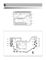
13. Motor 1. Remove the cabinet. (Refer to section 2) 2. Remove the evaporator. (Refer to section 4) 3. Remove the orifice. (Refer to section 4) 4. Remove the blower. (Refer to section 4) 5. Remove the fan. (Refer to section 5) 6. Remove the control box cover and disconnect 5 or 4 wires of motor housing. (Refer to section 3) 7. Remove the 2 or 4 screws that fasten the motor from the mount motor. (See Figure 28) 8. Remove the motor. 9. Re-install the components by referring to the removal procedure, above.(See Figure 28) Refrigerating Cycle CAUTION: Discharge the refrigerant system using a FreonTM Recovery System. If there is no valve to attach the recovery system, install one (such as a WATCO A-1) before venting the FreonTM. Leave the valve in place after servicing the system. 14. Condenser 1. Remove the cabinet. (Refer to section 2) 2. Remove the 4 screws that fasten the brace.(Refer to section 4) 3. Remove the 5 screws that fasten the condenser and shroud. 4. After discharging the refrigerant completely, unbraze the interconnecting tube at the condenser connections. 5. Remove the condenser. 6. Re-install the component by referring to notes. (See Figure 29) 15. Evaporator 1. Remove the cabinet. (Refer to section 2) 2. Remove the 2 screws that fasten the evaporator. 3. Move the evaporator sideways carefully. (Refer to section 4) 4. After discharging the refrigerant completely, unbraze the interconnecting tube at the evaporator connections. 5. Remove the evaporator. 6. Re-install the component by referring to notes. (See Figure 30) Disassembly Figure 28 Figure 29 Figure 30 Service Manual 19
-
 1
1 -
2
-
3
-
4
-
5
-
6
-
7
-
8
-
9
-
10
-
11
-
12
-
13
-
 14
14 -
 15
15 -
 16
16 -
 17
17 -
 18
18 -
 19
19 -
 20
20 -
 21
21 -
 22
22 -
 23
23 -
 24
24 -
25
-
26
-
27
-
28
-
29
-
30
-
31
 |
 |
