Lenovo K49 Hardware Maintenance Manual - Page 72
System board assembly, 1060 PCI Express Mini Card for wireless LAN
 |
View all Lenovo K49 manuals
Add to My Manuals
Save this manual to your list of manuals |
Page 72 highlights
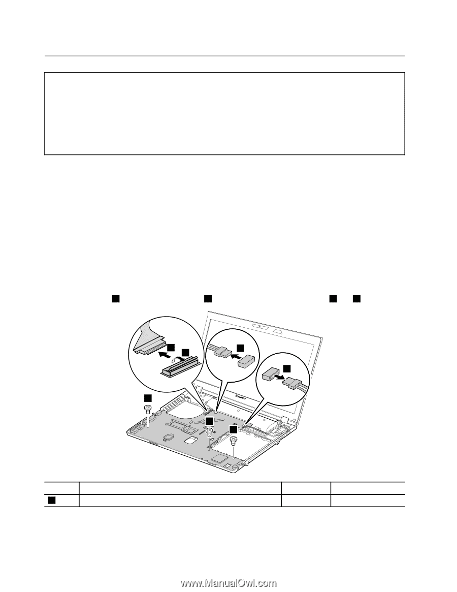
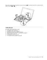
1170 System board assembly Important notices for handling the system board: When handling the system board, bear the following in mind: • Be careful not to drop the system board on a bench top that has a hard surface, such as metal, wood, or composite. • Avoid rough handling of any kind. • At every point in the process, be sure not to drop or stack the system board. • If you put a system board down, be sure to put it only on a padded surface such as an ESD mat or a corrugated conductive surface. For access, remove these FRUs in order: • "1010 Battery pack" on page 44 • "1020 Bottom slot cover" on page 44 • "1030 Optical drive or blank bezel" on page 45 • "1040 Memory modules" on page 46 • "1050 Hard disk drive assembly" on page 47 • "1060 PCI Express Mini Card for wireless LAN" on page 49 • "1070 mSATA solid-state drive (on some models)" on page 51 • "1100 Keyboard" on page 55 • "1110 Keyboard bezel" on page 58 • "1150 Backup battery" on page 63 • "1160 Speaker assembly" on page 64 Removal steps of system board assembly Remove the screws 1 . Then detach LCD cable 3 and speaker assembly connectors 4 and 5 . 3 2 4 5 1 1 1 Step 1 Screw (quantity) M2 × 3 mm, flat-head, nylon-coated (3) Color Black Torque 1.85 kgf-cm 66 Hardware Maintenance Manual
-
 1
1 -
2
-
3
-
4
-
5
-
6
-
7
-
8
-
9
-
10
-
11
-
12
-
13
-
14
-
15
-
16
-
17
-
18
-
19
-
20
-
21
-
22
-
23
-
24
-
25
-
26
-
27
-
28
-
29
-
30
-
31
-
32
-
33
-
34
-
35
-
36
-
37
-
38
-
39
-
40
-
41
-
42
-
43
-
44
-
45
-
46
-
47
-
48
-
49
-
50
-
51
-
52
-
53
-
54
-
55
-
56
-
57
-
58
-
59
-
60
-
61
-
62
-
63
-
64
-
65
-
66
-
 67
67 -
 68
68 -
 69
69 -
 70
70 -
 71
71 -
 72
72 -
 73
73 -
 74
74 -
 75
75 -
 76
76 -
 77
77 -
78
-
79
-
80
-
81
-
82
-
83
-
84
-
85
-
86
-
87
-
88
-
89
-
90
-
91
-
92
-
93
-
94
-
95
-
96
-
97
-
98
-
99
-
100
 |
 |