Lenovo K49 Hardware Maintenance Manual - Page 83
Removal steps of antenna assembly and LCD cover, Cable routing
 |
View all Lenovo K49 manuals
Add to My Manuals
Save this manual to your list of manuals |
Page 83 highlights
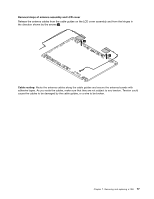
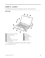
Removal steps of antenna assembly and LCD cover Release the antenna cables from the cable guides on the LCD cover assembly and from the hinges in the direction shown by the arrows 1 . 1 1 Cable routing: Route the antenna cables along the cable guides and secure the antenna boards with adhesive tapes. As you route the cables, make sure that they are not subject to any tension. Tension could cause the cables to be damaged by the cable guides, or a wire to be broken. Chapter 7. Removing and replacing a FRU 77
-
 1
1 -
2
-
3
-
4
-
5
-
6
-
7
-
8
-
9
-
10
-
11
-
12
-
13
-
14
-
15
-
16
-
17
-
18
-
19
-
20
-
21
-
22
-
23
-
24
-
25
-
26
-
27
-
28
-
29
-
30
-
31
-
32
-
33
-
34
-
35
-
36
-
37
-
38
-
39
-
40
-
41
-
42
-
43
-
44
-
45
-
46
-
47
-
48
-
49
-
50
-
51
-
52
-
53
-
54
-
55
-
56
-
57
-
58
-
59
-
60
-
61
-
62
-
63
-
64
-
65
-
66
-
67
-
68
-
69
-
70
-
71
-
72
-
73
-
74
-
75
-
76
-
77
-
 78
78 -
 79
79 -
 80
80 -
 81
81 -
 82
82 -
 83
83 -
 84
84 -
 85
85 -
 86
86 -
 87
87 -
 88
88 -
89
-
90
-
91
-
92
-
93
-
94
-
95
-
96
-
97
-
98
-
99
-
100
 |
 |
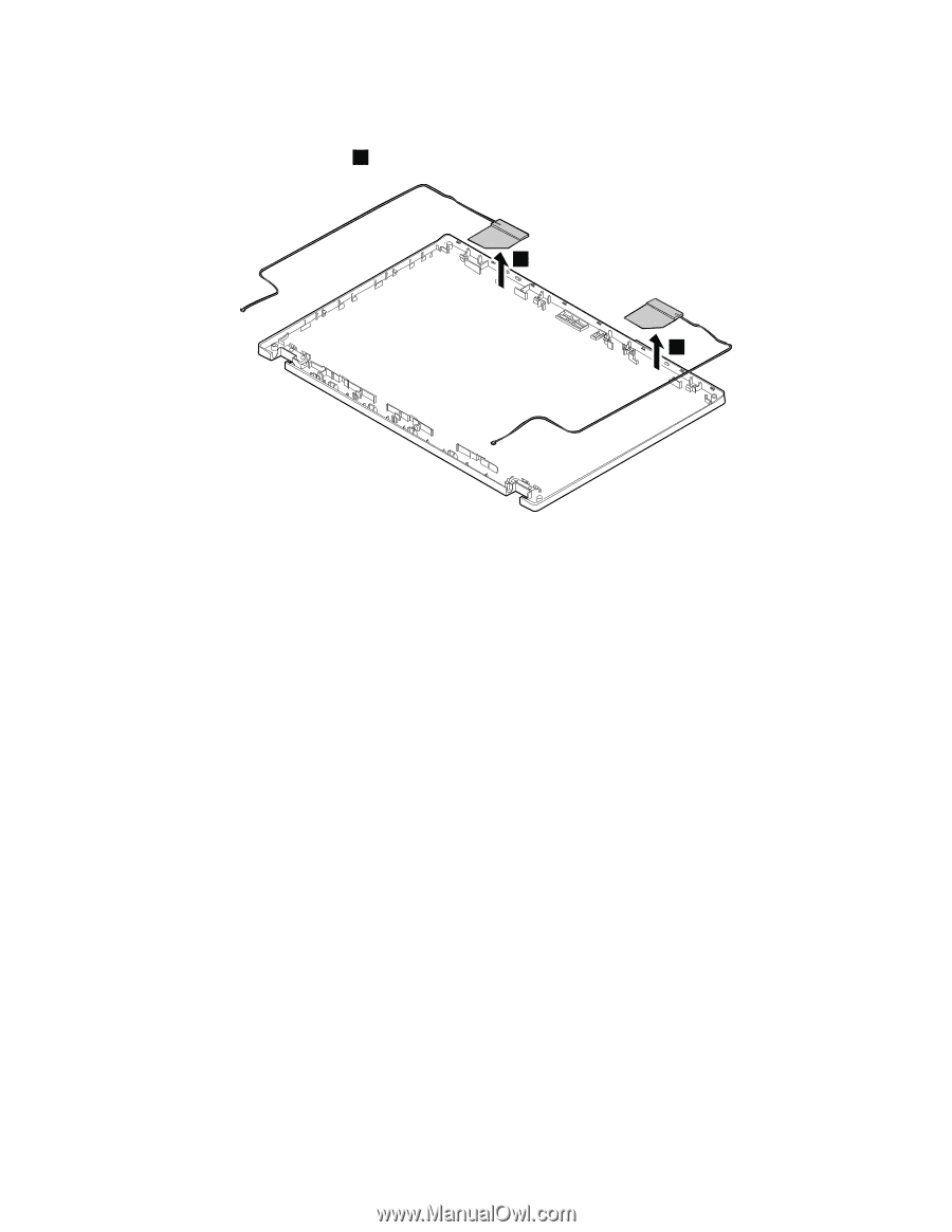
Removal steps of antenna assembly and LCD cover
Release the antenna cables from the cable guides on the LCD cover assembly and from the hinges in
the direction shown by the arrows
1
.
1
1
Cable routing:
Route the antenna cables along the cable guides and secure the antenna boards with
adhesive tapes. As you route the cables, make sure that they are not subject to any tension. Tension could
cause the cables to be damaged by the cable guides, or a wire to be broken.
Chapter 7
.
Removing and replacing a FRU
77