Lenovo ThinkPad R400 Hardware Maintenance Manual - Page 139
Accelerometer chip for the HDD Active Protection System, ICH I/O Controller Hub
 |
View all Lenovo ThinkPad R400 manuals
Add to My Manuals
Save this manual to your list of manuals |
Page 139 highlights
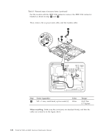
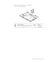
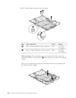
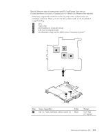
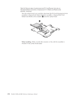
Table 28. Removal steps of system board and PC Card/Express Card slots (or ExpressCard/Smart Card slots or ExpressCard/7-in-1 Media Card Reader slots) assembly Following components soldered on the top side of the system board are extremely sensitive. When you service the system board, avoid any kind of rough handling. a CPU b Video chip c MCH (Memory Controller Hub) d ICH (I/O Controller Hub) e Accelerometer chip for the HDD Active Protection System™ b a c d e 1 1 Step 1 Screw (quantity) M2 × 2.7 mm, flat-head, nylon-coated (2) Color Black Torque 0.167 Nm (1.7 kgfcm) Removing and replacing a FRU 131
-
 1
1 -
2
-
3
-
4
-
5
-
6
-
7
-
8
-
9
-
10
-
11
-
12
-
13
-
14
-
15
-
16
-
17
-
18
-
19
-
20
-
21
-
22
-
23
-
24
-
25
-
26
-
27
-
28
-
29
-
30
-
31
-
32
-
33
-
34
-
35
-
36
-
37
-
38
-
39
-
40
-
41
-
42
-
43
-
44
-
45
-
46
-
47
-
48
-
49
-
50
-
51
-
52
-
53
-
54
-
55
-
56
-
57
-
58
-
59
-
60
-
61
-
62
-
63
-
64
-
65
-
66
-
67
-
68
-
69
-
70
-
71
-
72
-
73
-
74
-
75
-
76
-
77
-
78
-
79
-
80
-
81
-
82
-
83
-
84
-
85
-
86
-
87
-
88
-
89
-
90
-
91
-
92
-
93
-
94
-
95
-
96
-
97
-
98
-
99
-
100
-
101
-
102
-
103
-
104
-
105
-
106
-
107
-
108
-
109
-
110
-
111
-
112
-
113
-
114
-
115
-
116
-
117
-
118
-
119
-
120
-
121
-
122
-
123
-
124
-
125
-
126
-
127
-
128
-
129
-
130
-
131
-
132
-
133
-
 134
134 -
 135
135 -
 136
136 -
 137
137 -
 138
138 -
 139
139 -
 140
140 -
 141
141 -
 142
142 -
 143
143 -
 144
144 -
145
-
146
-
147
-
148
-
149
-
150
-
151
-
152
-
153
-
154
-
155
-
156
-
157
-
158
-
159
-
160
-
161
-
162
-
163
-
164
-
165
-
166
-
167
-
168
-
169
-
170
-
171
-
172
-
173
-
174
-
175
-
176
-
177
-
178
-
179
-
180
-
181
-
182
-
183
-
184
-
185
-
186
-
187
-
188
-
189
-
190
-
191
-
192
-
193
-
194
-
195
-
196
-
197
-
198
-
199
-
200
-
201
-
202
-
203
-
204
-
205
-
206
-
207
-
208
-
209
-
210
-
211
-
212
-
213
-
214
-
215
-
216
-
217
-
218
-
219
-
220
-
221
-
222
-
223
-
224
-
225
-
226
-
227
-
228
-
229
-
230
-
231
-
232
-
233
-
234
-
235
-
236
-
237
-
238
-
239
-
240
-
241
-
242
-
243
-
244
-
245
-
246
-
247
-
248
-
249
-
250
-
251
-
252
-
253
-
254
-
255
-
256
-
257
-
258
-
259
-
260
-
261
-
262
-
263
-
264
-
265
-
266
-
267
-
268
-
269
-
270
-
271
-
272
-
273
-
274
-
275
-
276
-
277
-
278
-
279
-
280
-
281
-
282
-
283
-
284
-
285
-
286
-
287
-
288
-
289
-
290
-
291
-
292
-
293
-
294
-
295
-
296
-
297
-
298
-
299
-
300
-
301
-
302
-
303
-
304
-
305
-
306
-
307
-
308
-
309
-
310
-
311
-
312
-
313
-
314
-
315
-
316
-
317
-
318
-
319
-
320
-
321
-
322
-
323
-
324
-
325
-
326
-
327
-
328
-
329
-
330
-
331
-
332
-
333
-
334
-
335
-
336
-
337
-
338
-
339
-
340
-
341
-
342
-
343
-
344
-
345
-
346
-
347
-
348
-
349
-
350
-
351
-
352
-
353
-
354
-
355
-
356
-
357
-
358
-
359
-
360
-
361
-
362
-
363
-
364
-
365
-
366
-
367
-
368
-
369
-
370
-
371
-
372
-
373
-
374
-
375
-
376
-
377
-
378
-
379
-
380
-
381
-
382
-
383
-
384
-
385
-
386
 |
 |
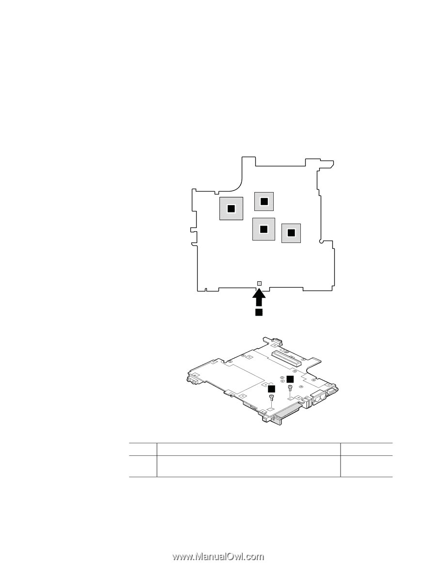
Table 28. Removal steps of system board and PC Card/Express Card slots (or
ExpressCard/Smart Card slots or ExpressCard/7-in-1 Media Card Reader slots) assembly
Following components soldered on the top side of the system board are
extremely sensitive. When you service the system board, avoid any kind of
rough handling.
±a²
CPU
±b²
Video chip
±c²
MCH (Memory Controller Hub)
±d²
ICH (I/O Controller Hub)
±e²
Accelerometer chip for the HDD Active Protection System
™
a
b
c
d
e
1
1
Step
Screw (quantity)
Color
Torque
±1²
M2
×
2.7 mm, flat-head, nylon-coated (2)
Black
0.167 Nm
(1.7 kgfcm)
Removing and replacing a FRU
131