Lexmark E360DN Service Manual - Page 144
Printhead removal, Top cover assembly removal
 |
UPC - 734646084475
View all Lexmark E360DN manuals
Add to My Manuals
Save this manual to your list of manuals |
Page 144 highlights
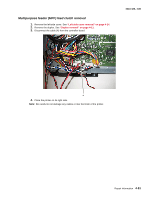
4513-420, -430 Printhead removal 1. Remove the top cover. See "Top cover assembly removal" on page 4-64. 2. Remove the right side cover. See "Right side cover assembly removal" on page 4-61 3. Disconnect the two cables (A), and unroute them back through the frame toward the printhead. A 4. Remove the three screws (B). Note: Use a pencil to mark the screw locations of the printhead on the metal frame. Align the new printhead relative to the location of the old printhead. See "Printhead assembly mechanical adjustment" on page 3-17. B 5. Remove the printhead. 4-56 Lexmark™ E360d, E360dn
-
 1
1 -
2
-
3
-
4
-
5
-
6
-
7
-
8
-
9
-
10
-
11
-
12
-
13
-
14
-
15
-
16
-
17
-
18
-
19
-
20
-
21
-
22
-
23
-
24
-
25
-
26
-
27
-
28
-
29
-
30
-
31
-
32
-
33
-
34
-
35
-
36
-
37
-
38
-
39
-
40
-
41
-
42
-
43
-
44
-
45
-
46
-
47
-
48
-
49
-
50
-
51
-
52
-
53
-
54
-
55
-
56
-
57
-
58
-
59
-
60
-
61
-
62
-
63
-
64
-
65
-
66
-
67
-
68
-
69
-
70
-
71
-
72
-
73
-
74
-
75
-
76
-
77
-
78
-
79
-
80
-
81
-
82
-
83
-
84
-
85
-
86
-
87
-
88
-
89
-
90
-
91
-
92
-
93
-
94
-
95
-
96
-
97
-
98
-
99
-
100
-
101
-
102
-
103
-
104
-
105
-
106
-
107
-
108
-
109
-
110
-
111
-
112
-
113
-
114
-
115
-
116
-
117
-
118
-
119
-
120
-
121
-
122
-
123
-
124
-
125
-
126
-
127
-
128
-
129
-
130
-
131
-
132
-
133
-
134
-
135
-
136
-
137
-
138
-
 139
139 -
 140
140 -
 141
141 -
 142
142 -
 143
143 -
 144
144 -
 145
145 -
 146
146 -
 147
147 -
 148
148 -
 149
149 -
150
-
151
-
152
-
153
-
154
-
155
-
156
-
157
-
158
-
159
-
160
-
161
-
162
-
163
-
164
-
165
-
166
-
167
-
168
-
169
-
170
-
171
-
172
-
173
-
174
-
175
-
176
-
177
-
178
-
179
-
180
 |
 |

4-56
Lexmark™ E360d, E360dn
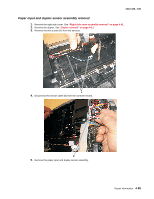
4513-420, -430
Printhead removal
1.
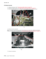
Remove the top cover. See
“Top cover assembly removal” on page 4-64
.
2.
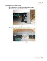
Remove the right side cover. See
“Right side cover assembly removal” on page 4-61
3.
Disconnect the two cables (A), and unroute them back through the frame toward the printhead.
4.
Remove the three screws (B).
Note:
Use a pencil to mark the screw locations of the printhead on the metal frame. Align the new printhead
relative to the location of the old printhead. See
“Printhead assembly mechanical adjustment” on page 3-17
.
5.
Remove the printhead.
A
B