Lexmark E360DN Service Manual - Page 161
-430, Connector, Value, cable plugged, if different, Comments, Open door sensor
 |
UPC - 734646084475
View all Lexmark E360DN manuals
Add to My Manuals
Save this manual to your list of manuals |
Page 161 highlights
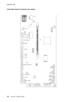
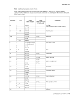
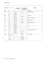
4513-420, -430 Note: See the wiring diagram at back of book. These values were measured with all connections made (plugged) or with only one connector at a time unplugged to expose the pins. Always disconnect and connect with the printer power off. Otherwise, the values below may not match. Connector Pin # J4 J5 J100 J7 J8 J9 J10 J11 J12 J13 J14 J17 J19 1 2 3, 4 1, 3, 5, 6 2 4, 7 1 2, 3 4, 5, 6, 7 1 2 3 1, 10 9 1 2 1 2 1 2 3 1 2 1 2 3 1 2 3 1, 4 2, 3, 6 5 7, 8, 9 Value cable plugged Value cable unplugged (if different) Comments Ground 1.7 V dc 3.3 V dc 3.3 V dc 5.0 V dc Ground > 0 V dc 5 V dc Ground 5 V dc (door closed) 0 V dc (door open) 5 V dc Ground 5 V dc 2.9 V dc 24 V dc 24 V dc 24 V dc 24 V dc 5 V dc Ground 5 V dc Ground 0.6 V dc Ground 0 V dc > 0 V dc 5 V dc Ground 0.1 V dc 5 V dc Ground 24 V dc 5 V dc 0 V dc 24 V dc 0 V dc 5 V dc 5 V dc 5 V dc 5 V dc Cartridge (The front access door must be closed.) Operator panel Printhead Open door sensor LSU Cooling fan Duplex solenoid Narrow media sensor Thermistor Toner level sensor Fuser exit sensor Main gear drive motor USB port Locations and connections 5-3
-
 1
1 -
2
-
3
-
4
-
5
-
6
-
7
-
8
-
9
-
10
-
11
-
12
-
13
-
14
-
15
-
16
-
17
-
18
-
19
-
20
-
21
-
22
-
23
-
24
-
25
-
26
-
27
-
28
-
29
-
30
-
31
-
32
-
33
-
34
-
35
-
36
-
37
-
38
-
39
-
40
-
41
-
42
-
43
-
44
-
45
-
46
-
47
-
48
-
49
-
50
-
51
-
52
-
53
-
54
-
55
-
56
-
57
-
58
-
59
-
60
-
61
-
62
-
63
-
64
-
65
-
66
-
67
-
68
-
69
-
70
-
71
-
72
-
73
-
74
-
75
-
76
-
77
-
78
-
79
-
80
-
81
-
82
-
83
-
84
-
85
-
86
-
87
-
88
-
89
-
90
-
91
-
92
-
93
-
94
-
95
-
96
-
97
-
98
-
99
-
100
-
101
-
102
-
103
-
104
-
105
-
106
-
107
-
108
-
109
-
110
-
111
-
112
-
113
-
114
-
115
-
116
-
117
-
118
-
119
-
120
-
121
-
122
-
123
-
124
-
125
-
126
-
127
-
128
-
129
-
130
-
131
-
132
-
133
-
134
-
135
-
136
-
137
-
138
-
139
-
140
-
141
-
142
-
143
-
144
-
145
-
146
-
147
-
148
-
149
-
150
-
151
-
152
-
153
-
154
-
155
-
 156
156 -
 157
157 -
 158
158 -
 159
159 -
 160
160 -
 161
161 -
 162
162 -
 163
163 -
 164
164 -
 165
165 -
 166
166 -
167
-
168
-
169
-
170
-
171
-
172
-
173
-
174
-
175
-
176
-
177
-
178
-
179
-
180
 |
 |
