Lexmark Forms Printer 2400 Service Manual - Page 83
Remove the carrier motor bracket from the print unit by pulling
 |
View all Lexmark Forms Printer 2400 manuals
Add to My Manuals
Save this manual to your list of manuals |
Page 83 highlights
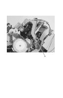
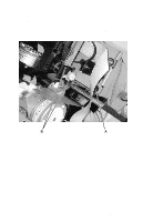
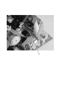
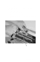
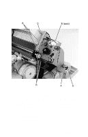
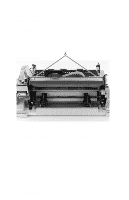
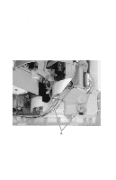
24xx 5. Remove the screw [A] securing the carrier motor bracket to the bottom cover. 6. Disconnect the printhead cable from the logic board and move it back and out of the way, as shown. 7. Remove the five screws [B] securing the carrier motor bracket to the print unit. 8. Remove the home position sensor [C] from the top of the carrier motor bracket by pinching the clips underneath the bracket. 9. Remove the carrier motor bracket from the print unit by pulling up and out on the rubber grommet [D] between the motor bracket and the bottom cover. 10. Disconnect the carrier motor cable from the logic board. 11. Remove the carrier motor from the motor bracket. Repair Information 4-23
-
 1
1 -
2
-
3
-
4
-
5
-
6
-
7
-
8
-
9
-
10
-
11
-
12
-
13
-
14
-
15
-
16
-
17
-
18
-
19
-
20
-
21
-
22
-
23
-
24
-
25
-
26
-
27
-
28
-
29
-
30
-
31
-
32
-
33
-
34
-
35
-
36
-
37
-
38
-
39
-
40
-
41
-
42
-
43
-
44
-
45
-
46
-
47
-
48
-
49
-
50
-
51
-
52
-
53
-
54
-
55
-
56
-
57
-
58
-
59
-
60
-
61
-
62
-
63
-
64
-
65
-
66
-
67
-
68
-
69
-
70
-
71
-
72
-
73
-
74
-
75
-
76
-
77
-
 78
78 -
 79
79 -
 80
80 -
 81
81 -
 82
82 -
 83
83 -
 84
84 -
 85
85 -
 86
86 -
 87
87 -
 88
88 -
89
-
90
-
91
-
92
-
93
-
94
-
95
-
96
-
97
-
98
-
99
-
100
-
101
-
102
-
103
-
104
-
105
-
106
-
107
-
108
-
109
-
110
-
111
-
112
-
113
-
114
-
115
-
116
-
117
-
118
-
119
-
120
-
121
-
122
-
123
-
124
-
125
-
126
-
127
-
128
-
129
-
130
-
131
-
132
-
133
-
134
-
135
-
136
-
137
-
138
-
139
-
140
-
141
-
142
-
143
-
144
-
145
-
146
-
147
-
148
-
149
-
150
-
151
-
152
-
153
-
154
-
155
-
156
-
157
-
158
-
159
-
160
-
161
-
162
-
163
-
164
-
165
-
166
-
167
-
168
-
169
-
170
 |
 |

Repair Information
4-23
24xx
5.
Remove the screw [
A
]
securing the carrier motor bracket to the
bottom cover.
6.
Disconnect the printhead cable from the logic board and move it
back and out of the way, as shown.
7.
Remove the five screws [
B
] securing the carrier motor bracket
to the print unit.
8.
Remove the home position sensor [
C
] from the top of the carrier
motor bracket by pinching the clips underneath the bracket.
9.
Remove the carrier motor bracket from the print unit by pulling
up and out on the rubber grommet [
D
] between the motor
bracket and the bottom cover.
10.
Disconnect the carrier motor cable from the logic board.
11.
Remove the carrier motor from the motor bracket.