LiftMaster 1355 1355 Manual
LiftMaster 1355 Manual
 |
View all LiftMaster 1355 manuals
Add to My Manuals
Save this manual to your list of manuals |
LiftMaster 1355 manual content summary:
- LiftMaster 1355 | 1355 Manual - Page 1
® GARAGE DOOR OPENER Model Series 1300 For Residential Use Only Model 1356 - 1/2HP Model 1346 - 1/3HP Model 1355 - 1/2HP Model 1345 - 1/3HP Owner's Manual ■ Please read this manual and the enclosed safety materials carefully! ■ Fasten the manual near the garage door after installation. ■ The door - LiftMaster 1355 | 1355 Manual - Page 2
Symbol and Signal Word Review This garage door opener has been designed and tested to offer safe service provided it is installed, operated, maintained and tested in strict accordance with the instructions and warnings contained in this manual. WARNING Mechanical WCAAURTNIOINNG WEAleRctNricINal - LiftMaster 1355 | 1355 Manual - Page 3
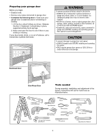
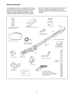
operate garage door opener at 120V, 60 Hz to avoid malfunction and damage. Sectional Door One-Piece Door Tools needed During assembly, installation and adjustment of the opener, instructions will call for hand tools as illustrated below. Carpenter's Level (Optional) 12 Tape Measure Pencil Wire - LiftMaster 1355 | 1355 Manual - Page 4
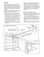
of your opener. Depending on your requirements, there are several installation steps which may call for materials or hardware not included in the carton. • Installation Step 1 - Look at the wall or ceiling above the garage door. The header bracket must be securely fastened to structural supports - LiftMaster 1355 | 1355 Manual - Page 5
Wall Slack in chain tension is normal when garage door is closed. FINISHED CEILING Support bracket & fastening hardware is required. See page 17. Motor Unit Wall-mounted Door Control Access Door Chain CLOSED POSITION Pulley Bracket Trolley Safety Reversing Sensor Safety Reversing Gap - LiftMaster 1355 | 1355 Manual - Page 6
until installation and adjustment is complete. Model 1355 & 1345 ONLY Lighted Door Control Button w/6ABx1-1/2" screws SECURITY✚® Single-Button Remote Control (1) Sprocket Cover Remote Control Transmitter Visor Clip Chain Styrofoam Motor Unit with Light Lens 2-Conductor Bell Wire White - LiftMaster 1355 | 1355 Manual - Page 7
Hardware Inventory Separate all hardware and group as shown below for the assembly and installation procedures. INSTALLATION HARDWARE Lag Screw 5/16"-9 x1-5/8" (2) Lag Screw 5/16"-18x1-7/8" (2) Hex Bolt 5/16"-18x7/8" (4) NOTICE Handle Self-Threading Screw 1/4"-14x5/8" (2) Drywall Anchors (2) - LiftMaster 1355 | 1355 Manual - Page 8
to garage door opener, use ONLY those bolts/fasteners mounted in the top of the opener. USE ONLY THIS TYPE AND SIZE BOLT Washered Bolt 5/16"-18x1/2" Rail Hole Styrofoam ASSEMBLY STEP 2 Attach the Chain to the Sprocket and Install the Sprocket Cover MODELS 1355 AND 1345 ONLY • Position chain over - LiftMaster 1355 | 1355 Manual - Page 9
. WARNING CAUTION To avoid SERIOUS damage to garage door opener, use ONLY those bolts/fasteners mounted in the top of the opener. Styrofoam Packaging Chain Rail Washered Bolts 5/16"-18x1/2" USE ONLY THIS TYPE AND SIZE BOLT Motor Unit Sprocket USE ONLY THIS TYPE AND SIZE BOLT Washered Bolts - LiftMaster 1355 | 1355 Manual - Page 10
shaft. Proceed to Assembly Step 3 for chain tightening instructions. WARNING To avoid possible SERIOUS INJURY to fingers from CAUTION moving garage door opener: • ALWAYS keep hand clear of sprocket while operating opener. • Securely attach sprocket cover BEFORE operating. USE ONLY THIS TYPE - LiftMaster 1355 | 1355 Manual - Page 11
connect garage door opener to power source until instructed to do so. 8. NEVER wear watches, rings or loose clothing while installing or servicing opener. They could be caught in garage door or opener mechanisms. 9. Install wall-mounted garage door control: • within sight of the garage door. • out - LiftMaster 1355 | 1355 Manual - Page 12
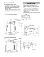
if necessary, to gain approximately 1/2" (1 cm).) If you need to install the header bracket on a 2x4 (on wall or ceiling), use lag screws (not provided) to securely fasten the 2x4 to structural supports as shown here and on page 13. 3. Open your door to the highest point of travel as shown. Draw an - LiftMaster 1355 | 1355 Manual - Page 13
install the header bracket on a 2x4 (on wall or ceiling), use lag screws (not provided) to securely fasten the 2x4 to structural supports as shown. 2. Open your door door.) Proceed to Step 2, page 14. Header Wall Unfinished Ceiling 2x4 Vertical Centerline of Garage Door Structural Supports 2x4 - LiftMaster 1355 | 1355 Manual - Page 14
garage door, or to the ceiling. Follow the instructions which will work best for your particular requirements. Do not install the header bracket over drywall. If installing Drill 3/16" pilot holes and fasten bracket securely to a structural support with the hardware provided. Ceiling Mounting Holes - LiftMaster 1355 | 1355 Manual - Page 15
Bracket INSTALLATION STEP 3 Attach the Rail to the Header Bracket • Position the opener on the garage floor below the header bracket. Use packing material as a protective base. NOTE: If the door spring is in the way you'll need help. Have someone hold the opener securely on a temporary support to - LiftMaster 1355 | 1355 Manual - Page 16
toward the motor unit. The trolley can remain disconnected until Installation Step 12 is completed. WARNING CAUTION To prevent damage to garage door, rest garage door opener rail on 2x4 placed on top section of door. Rail Door 2x4 is used to determine the correct mounting height from ceiling - LiftMaster 1355 | 1355 Manual - Page 17
WARNING To avoid possible SERIOUS INJURY from a falling CAUTION garage door opener, fasten it SECURELY to structural supports of the garage. Concrete anchors MUST be used if installing any brackets into masonry. Figure 1 Structural Supports Measure Distance Bolt 5/16"-18x7/8" Lock Washer 5/16 - LiftMaster 1355 | 1355 Manual - Page 18
Sensor instructions beginning on page 21. WARNING WARNING To prevent possible SERIOUS INJURY or DEATH from electrocution: • Be sure power is not connected BEFORE installing door control. • Connect ONLY to 24 VOLT low voltage wires. To prevent possible SERIOUS INJURY or DEATH from a closing garage - LiftMaster 1355 | 1355 Manual - Page 19
power is connected. Then the light will turn OFF. • Use standard neck Garage Door Opener bulbs for replacement INSTALL THE LENS • Locate and loosen (approximately 1/8" (3 mm) the two screws near top of opener front panel. • Position lens against panel with slotted tabs directly below screws. Slide - LiftMaster 1355 | 1355 Manual - Page 20
from WARNING electrocution or fire: • Be sure power is not connected to the opener, and disconnect power to circuit BEFORE removing cover to establish permanent wiring connection. • Garage door installation and wiring MUST be in compliance with all local electrical and building codes. • NEVER use - LiftMaster 1355 | 1355 Manual - Page 21
STEP 10 Install The Protector System® The safety reversing sensor must be connected and aligned correctly before the garage door opener will move in the down direction. IMPORTANT INFORMATION ABOUT THE SAFETY REVERSING SENSOR When properly connected and aligned, the sensor will detect an obstacle - LiftMaster 1355 | 1355 Manual - Page 22
sure power to the opener is disconnected. Install and align the brackets so the sensors will face each other across the garage door, with the beam no higher than 6" (15 cm) above the floor. They may be installed in one of three ways, as follows. Garage door track installation (preferred): • Slip the - LiftMaster 1355 | 1355 Manual - Page 23
door is already open, it will not close. The opener lights will blink 10 times. (If bulbs are not installed, 10 clicks can be heard.) See page 21. Figure 6 Bell Wire Finished Ceiling Connect Wire to Opener Terminal Screws Bell Wire Door Control Connections (dotted line) 1 Sensor Connections - LiftMaster 1355 | 1355 Manual - Page 24
brace. For the vertical brace, 2 pieces of angle iron are used to create a U-shaped support. The best solution is to check with your garage door manufacturer for an opener installation door reinforcement kit. NOTE: Many door reinforcement kits provide for direct attachment of the clevis pin and - LiftMaster 1355 | 1355 Manual - Page 25
may be installed on the top edge of the door if required for your installation. (Refer to the dotted line optional placement drawing.) Header Wall 2x4 Support Finished Ceiling Header Bracket Door Bracket Optional Placement of Door Bracket Vertical Centerline of Garage Door HORIZONTAL AND - LiftMaster 1355 | 1355 Manual - Page 26
INSTALLATION STEP 12 Connect Door Arm to Trolley Follow instructions which apply to your door type as illustrated below and on the following page. SECTIONAL DOORS ONLY • Make sure garage door is fully closed. Pull the emergency release handle to disconnect the outer trolley from the inner trolley. - LiftMaster 1355 | 1355 Manual - Page 27
- Turn the UP limit adjustment screw counterclockwise 5-1/2 turns. - Press the Door Control push button. The trolley will travel to the fully open position. - Manually raise the door to the open position (parallel to the floor), and lift the door arm to the trolley. The arm should touch the trolley - LiftMaster 1355 | 1355 Manual - Page 28
travel cycle: If the opener lights are flashing, the Safety Reversing Sensors are either not installed, misaligned, or obstructed. See Troubleshooting, page 23. Test the door for binding: Pull the emergency release handle. Manually open and close the door. If the door is binding or unbalanced, call - LiftMaster 1355 | 1355 Manual - Page 29
to open and close the door. If the forces are set too light, door travel doors), it will reverse. WARNING Without a properly installed safety reversal system, CAUTION persons (particularly small children) could be SERIOUSLY INJURED or KILLED by a closing garage door. • Too much force on garage door - LiftMaster 1355 | 1355 Manual - Page 30
to open the door. • Place the opener carton in the path of the door. • Press the remote control push button to close the door. The door will not move more than an inch, and the opener lights will flash. The garage door opener will not close from a remote if the indicator light in either sensor is - LiftMaster 1355 | 1355 Manual - Page 31
systems technician. 14. ALWAYS disconnect electric power to garage door opener BEFORE making any repairs or removing covers. 15. SAVE THESE INSTRUCTIONS. Using Your Garage Door Opener Your Security✚® opener and hand-held remote control have been factory-set to a matching code which changes with - LiftMaster 1355 | 1355 Manual - Page 32
Press the push button to open or close the door. Press again to reverse the door during the closing cycle or to stop the door while it's opening. To Open the Door Manually WARNING To prevent possible SERIOUS INJURY or DEATH from a CAUTION falling garage door: • If possible, use emergency release - LiftMaster 1355 | 1355 Manual - Page 33
the Door Control or the remote control: • Does the opener have electric power? Plug a lamp into the outlet. If it doesn't light, check the fuse box or the circuit breaker. (Some outlets are controlled by a wall switch.) • Have you disabled all door locks? Review installation instruction warnings - LiftMaster 1355 | 1355 Manual - Page 34
and opener lights blink for 5 seconds after reversing: • Check the safety reversing sensor. Remove any obstruction or align the receiving eye. See Installation Step 10. 12. The opener lights don't turn on: • Replace the light bulbs (75 watts maximum). Use A19 standard neck garage door opener bulb - LiftMaster 1355 | 1355 Manual - Page 35
to operate it. Additional buttons on any Security✚® 3-button remote or mini-remote can be programmed to operate other Security✚® garage door openers. 3. Release the button when the motor unit lights blink. It has learned the code. If light bulbs are not installed, two clicks will be heard. 35 - LiftMaster 1355 | 1355 Manual - Page 36
choice on the keypad. Then press and hold the ENTER button. To set a temporary PIN You may authorize access by visitors or service people with a temporary 4-digit PIN. After a programmed number of hours or number of accesses, this temporary PIN expires and will no longer open the door. It can be - LiftMaster 1355 | 1355 Manual - Page 37
eyes) with 3' (.9 m) 2-conductor bell wire attached 10 178B34 Straight door arm section 11 178B35 Curved door arm section 12 41A5266-1 Safety sensor brackets (2) Not shown 41A2770-6 Installation hardware bag (see page 7). 114A3072 Owner's manual 114A3072SP Owner's manual - Spanish 37 - LiftMaster 1355 | 1355 Manual - Page 38
11 13 (Down) Contact Brown Wire Drive Gear UP DN LIMIT SWITCH ASSY. Grey Wire Center Limit (Up) Contact Contact Yellow Wire KEY PART NO. NO. DESCRIPTION 1 41A4208-2 Chain spreader w/screws (1356, 1346) 1A 31D380 Sprocket cover (1355, 1345) 2 41C4206 Gear and sprocket assy. (1356, 1346) 2A - LiftMaster 1355 | 1355 Manual - Page 39
Mini-Remote Control with Security✚®: With key ring and fastening strip. 41A5281 Extension Brackets: (Optional) For safety sensor installation onto the wall or floor. 377LM 78LM LOCK LIGHT Multi-Function Door Control Panel: Provides a Lock Feature which prevents operation of garage door opener - LiftMaster 1355 | 1355 Manual - Page 40
: 1-800-528-2817 www.liftmaster.com For professional installation, parts and service, contact your local LIFTMASTER/CHAMBERLAIN dealer. Look for him in the Yellow Pages, or call our Service number for a list of dealers in your area. HOW TO ORDER REPAIR PARTS Selling prices will be furnished on
-
 1
1 -
 2
2 -
 3
3 -
 4
4 -
 5
5 -
 6
6 -
 7
7 -
8
-
9
-
10
-
11
-
12
-
13
-
14
-
15
-
16
-
17
-
18
-
19
-
20
-
21
-
22
-
23
-
24
-
25
-
26
-
27
-
28
-
29
-
30
-
31
-
32
-
33
-
34
-
35
-
36
-
37
-
38
-
39
-
40
 |
 |
The Chamberlain Group, Inc.
845 Larch Avenue
Elmhurst, Illinois 60126-1196
www.liftmaster.com
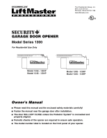
GARAGE DOOR OPENER
Model Series 1300
For Residential Use Only
Owner’s Manual
■
Please read this manual and the enclosed safety materials carefully!
■
Fasten the manual near the garage door after installation.
■
The door WILL NOT CLOSE unless the Protector System
®
is connected and
properly aligned.
■
Periodic checks of the opener are required to ensure safe operation.
■
The model number label is located on the front panel of your opener.
®
Model 1356 - 1/2HP
Model 1346 - 1/3HP
Model 1355 - 1/2HP
Model 1345 - 1/3HP