LiftMaster Dial Code Dial Code LC and VF Series Manual
LiftMaster Dial Code Manual
 |
View all LiftMaster Dial Code manuals
Add to My Manuals
Save this manual to your list of manuals |
LiftMaster Dial Code manual content summary:
- LiftMaster Dial Code | Dial Code LC and VF Series Manual - Page 1
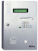
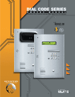
DIAL CODE SERIES OWNER S MANUAL Telephone entry systems with two line large LC or VF displays with B U I LT- I N surge suppression VISIT US ON THE WEB www.chamberlain.com - LiftMaster Dial Code | Dial Code LC and VF Series Manual - Page 2
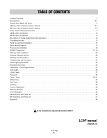
24 Transmitter / Card Programming 25 Area Codes 26 Utility Codes 27 Password 28 Clock / Timer 29-31 Strike Time 32 Talk Time 32 Greeting 33 Volume Adjustment 33 Back-Up Memory 34 Error Messages 35 LC Illustration and Parts List 36 VF Illustration and Parts List 37 Approvals 38 - LiftMaster Dial Code | Dial Code LC and VF Series Manual - Page 3
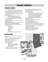
Battery enables dial out, program, & display. - Non-Volatile removable SRAM memory has unlimited write cycles (unlike EEPROM). - Non-Volatile Real Time Clock/Calendar. • High quality voice communication system with background noise filtering. • Voice messages (digital) to help & guide user. • Volume - LiftMaster Dial Code | Dial Code LC and VF Series Manual - Page 4
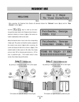
listed in the Telephone Entry System's electronic directory as shown in (fig c.) The names are listed in alphabetical order by last name. When the desired name is found, enter the corresponding 3-digit code. The system will dial the number assigned to the resident code entered. (fig d.) After - LiftMaster Dial Code | Dial Code LC and VF Series Manual - Page 5
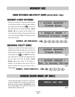
it is not within the time zone for entry, the * ACCESS DENIED * Not In Access Period display will inform the user and access will not be (fig d.) allowed (fig d.) EXAMPLE - UTILITY CODE 8716 = 8 71 6 SCREEN SAVER MODE (VF ONLY) If the VF Dial Code System is inactive for 15 seconds it will go - LiftMaster Dial Code | Dial Code LC and VF Series Manual - Page 6
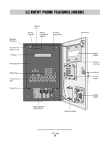
LC ENTRY PHONE FEATURES (INSIDE) Mounting Holes (4) Processor Key Release / Lock LC Display Processor Unit Dialing Keys Programming Keys Parallel Port Memory Card Memory Card Slot Memory Card Release Speaker All components and specifications are subject to change without notice. LC/VF Page 5 - LiftMaster Dial Code | Dial Code LC and VF Series Manual - Page 7
LC ENTRY PHONE FEATURES (OUTSIDE) 1 EXTERNAL MICROPHONE 1 2 KEY LOCK - Opens the Processor Containment Box to access the Processor. 3 HELP KEY - With digital voice messages to 5 help guide the user. 4 EXTERNAL SPEAKER 5 DISPLAY WINDOW - Heavy-duty, 3/8" thick protective lens. 6 6 DIALING - LiftMaster Dial Code | Dial Code LC and VF Series Manual - Page 8
VF ENTRY PHONE FEATURES (INSIDE) Mounting Holes (4) Processor Key Release / Lock VF Display Processor Unit Dialing Keys Programming Keys Parallel Port Memory Card Memory Card Slot Memory Card Release Buttons Processor Power Switch Microphone Display Hood Display Window Stainless Steel Door Key - LiftMaster Dial Code | Dial Code LC and VF Series Manual - Page 9
VF ENTRY PHONE FEATURES (OUTSIDE) 1 EXTERNAL MICROPHONE 1 2 KEY LOCK - Opens the Processor Containment Box to access the Processor. 6 3 HELP KEY - With digital voice messages to 5 help guide the user. 4 EXTERNAL SPEAKER 5 DISPLAY WINDOW - Heavy-duty, 3/8" thick protective lens. 7 6 - LiftMaster Dial Code | Dial Code LC and VF Series Manual - Page 10
Cards when pressed. 5 MAIN MEMORY CARD SLOT - Holds Main Memory Card. 6 RS485 MEMORY CARD SLOT - Holds RF Communicator Card or Backup Memory. 7 LCD TWO LINE, LARGE LIQUID CRYSTAL DISPLAY OR VF SUPER BRIGHT VACUUM FLUORESCENT DISPLAY SCREEN- Displays information and instructions, two lines at a time - LiftMaster Dial Code | Dial Code LC and VF Series Manual - Page 11
41/8 " Be sure to read and follow all Chamberlain Elite instructions before installating and operating any Chamberlain Elite products. Not responsible for improper installations or failure to comply with local building codes - LiftMaster Dial Code | Dial Code LC and VF Series Manual - Page 12
l occur Please refer to he owners manual for proper ground ng instruct ons e it entr phone com MADE IN USA POWER GATE RELAY DOOR RELAY 8 3/4" 1/4 " 41/8 " 3" Be sure to read and follow all Chamberlain Elite instructions before installating and operating any Chamberlain Elite products. Not - LiftMaster Dial Code | Dial Code LC and VF Series Manual - Page 13
Installation" sections. 9 POWER LED: Indicates Phone system has 12 Vac power. 10 GATE RELAY LED: Indicates gate relay is activated. 11 DOOR RELAY LED: Indicates door relay is activated. 12V AC/DC POWER IN NOTE: Telephone line used for Telephone Entry System must be a dedicated line. LC/VF Page 12 - LiftMaster Dial Code | Dial Code LC and VF Series Manual - Page 14
occur. Please refer to the owners manual for proper grounding instructions. eliteentryphone com MADE N USA POWER GATE RELAY DOOR RELAY Ground Rod Refer to the next page for ground rod installation. LC/VF - LiftMaster Dial Code | Dial Code LC and VF Series Manual - Page 15
directed towards the Telephone Entry System (TES). can protect the Telehone Entry System in most cases. System The earth ground rod must be located within 3 feet from the TES System. For the correct wire gauge, consult the local code code Chamberlain Elite is not responsible for improper installation - LiftMaster Dial Code | Dial Code LC and VF Series Manual - Page 16
the phone system ONLY! NOTE: Installation where fiber optic cables are present may require additional modifications from your telephone provider. Strike Open Input) Access Door Solenoid OR OR Entry Door Maglock Dial Dial Connect two wires to the main vehicular gate operator LC/VF Page 15 - LiftMaster Dial Code | Dial Code LC and VF Series Manual - Page 17
Stainless Steel Front Panel of Telephone Entry System Postal Lock Postal Lock manual for proper grounding instructions. MADE IN USA Installation: 1 Open the front panel of the Telephone Entry System polarity or color coding is not required. When the postal lock is engaged, the system's gate relay - LiftMaster Dial Code | Dial Code LC and VF Series Manual - Page 18
transmission) • Up to 31 RS485 devices supported • Maximum distance from the last RS485 device to the Telephone Entry System is 4000 Ft. • Turn "ON" the must have a unique "Device ID Number" set by using the rotary switches on the device. (Refer to specific RS485 Instruction sheets). LC/VF Page 17 - LiftMaster Dial Code | Dial Code LC and VF Series Manual - Page 19
Elite Entry Phone Main Me Card Slot RS485 Memory Card Slot RS485 Card Release Button NOTE: To support RS485 devices you must insert the RF communicator card in the RS485 memory refer to the owners manual for proper grounding instructions. eliteentryphone.com MADE IN USA POWER GATE RELAY DOOR - LiftMaster Dial Code | Dial Code LC and VF Series Manual - Page 20
Elite Entry Phone Main M ard Slot RS485 Memory Card Slot Use 22 AWG Twisted Pair Shielded Wire Keypad RS485 Remote Device 1 (+) (-) Ground RS485 Card Release Button NOTE: To support to the owners manual for proper grounding instructions. eliteentryphone.com MADE IN USA POWER GTAE RELAY DOOR - LiftMaster Dial Code | Dial Code LC and VF Series Manual - Page 21
an information screen is accessible on all Dial Code systems for easy reference. Turn power off and insert Memory Card in Main Memory Slot. Turn power on and the information screen should display as seen in (fig e.) DIAL CODE LC-250 REV. 1.00_ (fig e.) Software Version Number LC/VF Page 20 - LiftMaster Dial Code | Dial Code LC and VF Series Manual - Page 22
drop or expose to impact. ENTER ERASE EX T Q PROGRAM E W S R D A X SHIFT Z SPACE BAR 3 2 1 6 5 4 9 8 7 0 I HELP T U Y J H G N F B V C O K M P L BSAPACCKE ' The Telephone Entry System is only water resistant when the Stainless Steel Door is closed and locked. Do not - LiftMaster Dial Code | Dial Code LC and VF Series Manual - Page 23
message. IMPORTANT NOTE: While in the help screens, programming will be disabled. To continue programming, press the button to exit the help screens first. LC/VF Page 22 - LiftMaster Dial Code | Dial Code LC and VF Series Manual - Page 24
System Clock and Seven Day Timers pages 29-31 S Program relay output time ( for 2 relays ) page 32 T Program length of Talk Time page 32 G Program custom Welcome Screen Message page 33 V Program Volume level page 33 B Backup of memory to exit the help screens first. LC/VF Page 23 - LiftMaster Dial Code | Dial Code LC and VF Series Manual - Page 25
existing name the N key and the first OR a three digit code* and press OR or code, use the empty code will display. the key. keys to scroll through Directory. * The unit will only accept codes within it's range - depending on memory capacity. 3 STEP Type in the desired Resident name, LAST - LiftMaster Dial Code | Dial Code LC and VF Series Manual - Page 26
entry, Memory Card Installation" section) 7 STEP Use keys to view and program up to 10 transmitter or card codes associated to the directory code. To program a transmitter or card code you may enter the code manually for up to ten devices per directory code. After the last device has been - LiftMaster Dial Code | Dial Code LC and VF Series Manual - Page 27
change the prefix to any number. To choose 8, 9, or 10-digit dialing, when no prefix is needed, press while in the prefix field. Then type the required number of digits in the area code field followed by the phone number. Press the key to continue with the entry as described in the "Resident - LiftMaster Dial Code | Dial Code LC and VF Series Manual - Page 28
, telephone, construction companies, water, power, etc. These utilities can use their individual code to access the premises within the time zone that you program. Each system, no matter what the memory capacity To continue programming, press the button to exit the help screens first. LC/VF Page 27 - LiftMaster Dial Code | Dial Code LC and VF Series Manual - Page 29
message. IMPORTANT NOTE: While in the help screens, programming will be disabled. To continue programming, press the button to exit the help screens first. LC/VF Page 28 - LiftMaster Dial Code | Dial Code LC and VF Series Manual - Page 30
between the three different menu choices (fig b.). Select the number of your The key will complete the date and time entry. (fig e.) SELECT PROG MODE: (C)Clock/Timer 02-11-2000 Time>07:31am p=pm (fig c.) Today Is THURSDAY Use To Select Day (fig d.) Daylight Savings>y (Y)Yes (N)No (fig e.) LC/VF - LiftMaster Dial Code | Dial Code LC and VF Series Manual - Page 31
3 to program the Door Timers Menu. Setup New Timers> N View/Edit Timers> See next page for instructions USE ARROWS TO VIEW / PROGRAM INDIVIDUAL TIME ZONES Use to view and program timer(s) for Sunday through Saturday. programming, press the button to exit the help screens first. LC/VF Page 30 - LiftMaster Dial Code | Dial Code LC and VF Series Manual - Page 32
Door Timers Menu Setup New Timers> N View/Edit Timers> PRESS N TO PROGRAM SETS OF TIME ZONES See previous page for instructions Program timers 1 and 2 for any day of the week (fig d.) Press N to turn timer 1 ON or press F , press the button to exit the help screens first. LC/VF Page 31 - LiftMaster Dial Code | Dial Code LC and VF Series Manual - Page 33
01-99] 10 Seconds [01-12] 05 Seconds (fig c.) (fig d.) DOOR NAME/LOCATION GATE NAME/LOCATION South Entry Door North Side Gate (fig e.) (fig f.) For either the Gate or Door Strike TIme, you may now type , or C for 80 seconds (fig h.). Press the key to confirm your entry. LC/VF Page 32 - LiftMaster Dial Code | Dial Code LC and VF Series Manual - Page 34
The system will automatically center your entry on the Welcome screen.(fig b.) SELECT PROG MODE: (G)Greeting (fig a.) FACILITY NAME: Woodbridge Meadows (fig b.) VOLUME ADJUST Use the Volume Screen to adjust both call and unit message volume levels. In the Program Selection Screen (fig c.), Press - LiftMaster Dial Code | Dial Code LC and VF Series Manual - Page 35
memory card in the Backup Slot. NOTE: Back-up Memory card must be the same size or greater than the Main Memory (fig a.) NOTE: You must have an extra memory card (sold separately) installed in the RS485 Slot 05-15-01 03:50am (fig c.) BACKUP Card Updated 02-11-01 04:20am (fig d.) (ENTER) To Backup - LiftMaster Dial Code | Dial Code LC and VF Series Manual - Page 36
to it is an "M" or a "C", as shown in (fig d.) and (fig e.), contact Manufacturer for instructions. C WELCOME (fig d.) WELCOME M (fig e.) *IMPORTANT NOTE: In order to charge the battery in the Dial Code System, the processor MUST be plugged in to the transformer and the processor MUST BE ON - LiftMaster Dial Code | Dial Code LC and VF Series Manual - Page 37
LC Complete Internal Metal Box (Processor Box) Programming Keys Postal Lock Assembly LCD Processor - No Memory Card Key for Internal / External Dial Code Surge Protection Board 25 Name Memory Card 50 Name Memory Card 150 Name Memory Card 250 Name Memory Card 500 Name Memory Card 1000 Name Memory - LiftMaster Dial Code | Dial Code LC and VF Series Manual - Page 38
RFCARD16K Key for Internal / External Lock Kit for Keypad Light Phone Control Board (Inside Processor) VF External Box Assembly Heater Pad Option (Pre-Installed in Processor) Keypad Light Speaker 4 OHM Dial Code Surge Protection Board 25 Name Memory Card 50 Name Memory Card 150 Name Memory Card 250 - LiftMaster Dial Code | Dial Code LC and VF Series Manual - Page 39
the equipment. User should ensure for their own protection, that the electrical ground connections of the power utility, telephone lines and internal metallic water pipe system, if present, are connected together. This precaution may be particularly important in rural areas." Caution: Users should - LiftMaster Dial Code | Dial Code LC and VF Series Manual - Page 40
114A2866F © 2008 The Chamberlain Group, Inc. - All Rights Reserved 845 Larch Avenue Elmhurst, Illinois 60126-1196
-
 1
1 -
 2
2 -
 3
3 -
 4
4 -
 5
5 -
 6
6 -
 7
7 -
8
-
9
-
10
-
11
-
12
-
13
-
14
-
15
-
16
-
17
-
18
-
19
-
20
-
21
-
22
-
23
-
24
-
25
-
26
-
27
-
28
-
29
-
30
-
31
-
32
-
33
-
34
-
35
-
36
-
37
-
38
-
39
-
40
 |
 |
DIAL CODE SERIES
O
W
N
E
R
S
M
A
N
U
A
L
Telephone entry systems with two line large LC or VF displays
www.chamberlain.com
VISIT US ON THE WEB
with
surge suppression
BUILT-IN