LiftMaster Dial Code Dial Code LC and VF Series Manual - Page 18
RS485 CONNECTION CONFIGURATIONS, Configuration #1, Daisy Chain
 |
View all LiftMaster Dial Code manuals
Add to My Manuals
Save this manual to your list of manuals |
Page 18 highlights
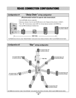
RS485 CONNECTION CONFIGURATIONS Configuration #1 "Daisy Chain" wiring configuration (Recommended method for superior data transmission) • Up to 31 RS485 devices supported • Maximum distance from the last RS485 device to the Telephone Entry System is 4000 Ft. • Turn "ON" the terminator switch ONLY for the last device installed in the RS485 line. • Use 22 AWG twisted pair shielded wire Turn Terminator Switch "ON" for Last Device on Wire Run Gnd + - 4000 Ft Max. Each RS485 device must have a unique "Device ID Number" set by using the rotary switches on the device. (Refer to specific RS485 Instruction sheets). Configuration #2 Turn Terminator Switch "ON" for Last Device on Wire Run "Star" wiring configuration Turn Terminator Switch "ON" for Last Device on Wire Run - + Gnd Wire Run Turn Terminator Switch "ON" for Last Device on Wire Run 4000 Ft Max. Turn Terminator Switch "ON" for Last Device on Wire Run Turn Terminator Switch "ON" for Last Device on Wire Run Turn Terminator Switch "ON" for Last Device on Wire Run Each RS485 device must have a unique "Device ID Number" set by using the rotary switches on the device. (Refer to specific RS485 Instruction sheets). LC/VF Page 17
-
 1
1 -
2
-
3
-
4
-
5
-
6
-
7
-
8
-
9
-
10
-
11
-
12
-
 13
13 -
 14
14 -
 15
15 -
 16
16 -
 17
17 -
 18
18 -
 19
19 -
 20
20 -
 21
21 -
 22
22 -
 23
23 -
24
-
25
-
26
-
27
-
28
-
29
-
30
-
31
-
32
-
33
-
34
-
35
-
36
-
37
-
38
-
39
-
40
 |
 |
