LiftMaster Dial Code Dial Code LC and VF Series Manual - Page 12
Vf Mounting Installation - for usa
 |
View all LiftMaster Dial Code manuals
Add to My Manuals
Save this manual to your list of manuals |
Page 12 highlights
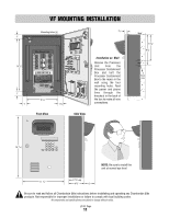
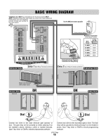
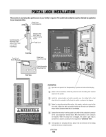
VF MOUNTING INSTALLATION Mounting Holes (4) 3/4" 1" 14 1/2" 1" 1" Wire Knock Outs TEL LINE RS-485 (1 RS-485 (2 RS-485 (3 RS-485 (4 TP RING +) -) GND +) -) GND (+) -) GND (+) -) GND 12V AC DC POWER NPUT DOOR-NO DOOR-NC DOOR-C GATE NO GATE NC GATE C VCR-NO VCR C CHASSIS GROUND GND NPUT DOOR RELAY GATE RELAY VCR RELAY POS AL/E IT SW INPUT It is MANDATORY that his un t is properly grounded The prov ded "chass s g ound" wire must be connec ed to he ground rod If unit is not grounded lightning damage wi l occur Please refer to he owners manual for proper ground ng instruct ons e it entr phone com MADE IN USA POWER GATE RELAY DOOR RELAY 8 3/4" 1 1/2" Front View Installation on Wall Remove the Processor Unit from the Processor Containment Box and bolt the Processor Containment Box to the recess in the wall using the four mounting holes. Feed the power and phone lines through the knockout in the back of the box to make all wire connections. Side View Wall 6 7/8" 8 1/4" Knock Outs 16 7/16" 123 456 789 0 NOTE: Be sure to install the unit at normal eye level 11 1/4 " 3 1/4 " 41/8 " 3" Be sure to read and follow all Chamberlain Elite instructions before installating and operating any Chamberlain Elite products. Not responsible for improper installations or failure to comply with local building codes. All components and specifications are subject to change without notice. LC/VF Page 11
-
 1
1 -
2
-
3
-
4
-
5
-
6
-
 7
7 -
 8
8 -
 9
9 -
 10
10 -
 11
11 -
 12
12 -
 13
13 -
 14
14 -
 15
15 -
 16
16 -
 17
17 -
18
-
19
-
20
-
21
-
22
-
23
-
24
-
25
-
26
-
27
-
28
-
29
-
30
-
31
-
32
-
33
-
34
-
35
-
36
-
37
-
38
-
39
-
40
 |
 |
