LiftMaster Dial Code Dial Code LC and VF Series Manual - Page 13
Description Of Surge Suppression Terminal Board - usa
 |
View all LiftMaster Dial Code manuals
Add to My Manuals
Save this manual to your list of manuals |
Page 13 highlights
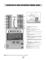
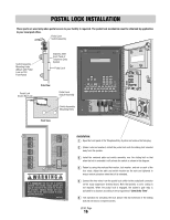
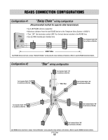
DESCRIPTION OF SURGE SUPPRESSION TERMINAL BOARD 1 TEL LINE RS485 (1) 3 RS485 (2) 3 RS485 (3) 3 RS485 (4) 3 TIP RING (+) (-) GND (+) (-) GND (+) (-) GND (+) (-) GND Knockouts for Incoming Wires 12V AC/DC DOOR-NO DOOR-NC DOOR-C GATE-NO GATE-NC GATE-C VCR-NO VCR-C CHASSIS GROUND GND INPUT POWER INPUT 2 DOOR RELAY 4 GATE RELAY 5 VCR RELAY 6 POSTAL/EXIT SW INPUT 7 8 It is MANDATORY that this unit is properly grounded. The provided "chassis ground" wire must be connected to the ground rod. If unit is not grounded, lightning damage will occur. Please refer to the owners manual for proper grounding instructions. eliteentryphone.com MADE IN USA 9 POWER GATE 10 RELAY DOOR 11 RELAY Removable Screw Terminal Connectors for Easy Wiring. 1 TELEPHONE LINE: Tip and Ring Connection. 2 POWER IN: 12 Vac transformer input. 3 RS485: Connect to corresponding RS485 terminals (-, +, GND) of remote security devices. 4 DOOR RELAY: For allowing access through pedestrian gate or door. 5 GATE RELAY: For use with gate operator to control access through main vehicular gate. 6 VCR RELAY: For use with Time Lapse VCR. Each time access is granted, the VCR Relay is activated for 5 seconds, allowing recording of all access to facility. 7 POSTAL/EXIT SW INPUT: For allowing postal lock access to pedestrian gate or door. Activates gate relay using gate strike time. 8 CHASSIS GROUND: Entry Phone MUST be properly grounded. Refer to "Grounding the Unit" and " Earth Ground Rod Installation" sections. 9 POWER LED: Indicates Phone system has 12 Vac power. 10 GATE RELAY LED: Indicates gate relay is activated. 11 DOOR RELAY LED: Indicates door relay is activated. 12V AC/DC POWER IN NOTE: Telephone line used for Telephone Entry System must be a dedicated line. LC/VF Page 12
-
 1
1 -
2
-
3
-
4
-
5
-
6
-
7
-
 8
8 -
 9
9 -
 10
10 -
 11
11 -
 12
12 -
 13
13 -
 14
14 -
 15
15 -
 16
16 -
 17
17 -
 18
18 -
19
-
20
-
21
-
22
-
23
-
24
-
25
-
26
-
27
-
28
-
29
-
30
-
31
-
32
-
33
-
34
-
35
-
36
-
37
-
38
-
39
-
40
 |
 |
