LiftMaster Dial Code Dial Code LC Series Manual - Page 11
Postal Lock Installation, Installation
 |
View all LiftMaster Dial Code manuals
Add to My Manuals
Save this manual to your list of manuals |
Page 11 highlights
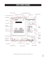
POSTAL LOCK INSTALLATION These parts are used only when postal access to your facility is required. The postal lock mechanism must be obtained by application to your local post office. Installation: Open the front panel of the Entry Phone and remove the hole plug. POSTAL LOCK SWITCH WIRES (2) POSTAL LOCK SWITCH ASSEMBLY KNOCK OUT HOLE FOR POSTAL LOCK SWITCH ASSEMBLY MOUNTING HOLES (MOUNT WITH POSTAL LOCK ON ENTRY PHONE FRONT PANEL) STAINLESS STEEL FRONT PANEL (Retain nuts and washers) Install the postal lock with the sliding bolt oriented away from the speaker. Install the enclosed plate end switch assembly over the sliding bolt so that when the bolt is extended it will activate the switch as shown in the diagram. POSTAL LOCK Fasten by using the enclosed flat washer, lock washer, and nut on each of the four studs. Adjust the plate and switch location as the nuts are tightened to ensure switch activation when the bolt is extended. Connect the two wires from the postal lock switch in parallel with either the two blue wires (door relay) or the two yellow wires (gate relay) at the 15 pin input/output connector. Note that polarity or color coding is not required. As example: If you wish to activate the door using the postal lock switch, connect wire 1 from the switch to one of the blue wires and connect wire 2 from the switch to the other blue wire. Test operation by activating the lock. Ensure that full extension of the sliding bolt will not bend or break the switch. PAGE 10
-
 1
1 -
2
-
3
-
4
-
5
-
 6
6 -
 7
7 -
 8
8 -
 9
9 -
 10
10 -
 11
11 -
 12
12 -
 13
13 -
 14
14 -
 15
15 -
 16
16 -
17
-
18
-
19
-
20
-
21
-
22
-
23
-
24
-
25
-
26
-
27
-
28
-
29
-
30
-
31
-
32
-
33
-
34
 |
 |
