LiftMaster Dial Code Dial Code LC Series Manual - Page 8
Entry Phone Features (Processor), MEMORY CARD RELEASE BUTTONS
 |
View all LiftMaster Dial Code manuals
Add to My Manuals
Save this manual to your list of manuals |
Page 8 highlights
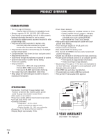
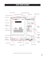
ENTRY PHONE FEATURES 13 POWER ON/OFF SWITCH 14 MEMORY CARD RELEASE BUTTONS - Eject Memory Cards when pressed. 15 CARD SLOTS - Front slot holds Backup Memory Card or RF Card, back slot holds Main Memory Card. 16 15 14 17 13 16 MEMORY CARD - Stores all programmed information. 17 TWO LINE, LARGE LIQUID CRYSTAL DISPLAY Displays information and instructions, two lines at a time. 18 DIRECTION KEYS - Move cursor to desired position within screens. 19 HELP KEY - Helps user while in programming or user modes. 20 ERASE KEY - Erases information screens no longer needed. 21 EXIT KEY - Press this key to go back to previous screen / menu. 18 22 PROGRAM KEY - Sets Processor to program 19 mode. 29 20 23 ENTER KEY - Registers information into memory after it is typed. 28 24 PRINTER PARALLEL PORT - Enables printing of 21 programmed information. 22 25 COMMUNICATION PORT - RF Interface for future remote control and card access use. 23 24 25 26 27 26 INPUT/OUTPUT CONNECTOR - Main power, input/output connection. 27 PHONE JACK (RJ11) - Connects to main phone line. 28 KEYBOARD - Works like standard keyboard to type in information and names. 29 SCROLL KEYS - Scrolls through screens / menus. All components and specifications are subject to change without notice. PAGE 7
-
 1
1 -
2
-
 3
3 -
 4
4 -
 5
5 -
 6
6 -
 7
7 -
 8
8 -
 9
9 -
 10
10 -
 11
11 -
 12
12 -
 13
13 -
14
-
15
-
16
-
17
-
18
-
19
-
20
-
21
-
22
-
23
-
24
-
25
-
26
-
27
-
28
-
29
-
30
-
31
-
32
-
33
-
34
 |
 |
