LiftMaster SW470 SW490 GL BOARD Manual - Page 23
Control Board Illustration
 |
View all LiftMaster SW470 manuals
Add to My Manuals
Save this manual to your list of manuals |
Page 23 highlights
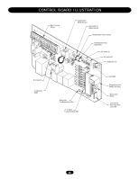
CONTROL BOARD ILLUSTRATION Main Terminal Wiring J4 Connector Master/Second Dip Switch #4 Master/Second Potentiometer Timer-to-Close Potentiometer Force Adjustment Dip Switch #2 Dip Switch #1 Diagnostic LED J2 Connector J5 Connector SAMS Relay Drive Troubleshooting LEDs J1 Terminal Troubleshooting LEDs Limit LEDs Programming Port (factory use only) Motor Learn Button J3 Connector Aux. Relay Drive (not used) 23
-
 1
1 -
2
-
3
-
4
-
5
-
6
-
7
-
8
-
9
-
10
-
11
-
12
-
13
-
14
-
15
-
16
-
17
-
 18
18 -
 19
19 -
 20
20 -
 21
21 -
 22
22 -
 23
23 -
 24
24 -
 25
25 -
 26
26 -
 27
27 -
 28
28 -
29
-
30
-
31
-
32
-
33
-
34
-
35
-
36
-
37
-
38
-
39
-
40
 |
 |

23
CONTROL BOARD ILLUSTRATION
Relay Drive
Troubleshooting LEDs
J1 Terminal
Troubleshooting LEDs
J5 Connector
SAMS
J2 Connector
J3 Connector
Aux. Relay Drive
(not used)
Motor Learn
Button
Programming Port
(factory use only)
Limit LEDs
Main Terminal
Wiring
Potentiometer Timer-to-Close
Dip Switch #4
Master/Second
J4 Connector
Master/Second
Diagnostic LED
Dip Switch #2
Dip Switch #1
Potentiometer Force
Adjustment